Packaging Editor (vers. 6)
PACKAGING PARAMETER MODIFICATION AND RELEASE FOR PERSONALIZATION
Open the Package Editor via the Data center - PackageEditor link and select the desired model under “Model“ at the top. Click Load Model in order to load the desired model. Click Render Model to visualize the model on the right.
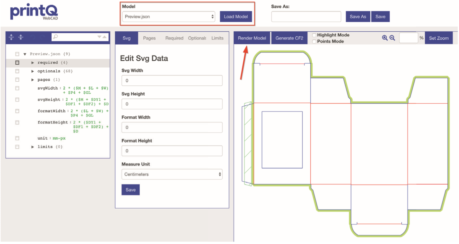
The individual parameters can be changed via the path structure on the left.
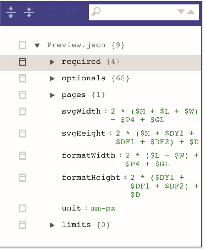
If you wish for your customers to be able to modify the packaging, the section “Required“ becomes relevant. Parameters created or modified here determine which values are mandatory for the configuration of the packaging. You will find the following input fields:
Name
The name for the field or the parameter is defined here (e.g. „Length“). It may only be assigned once.
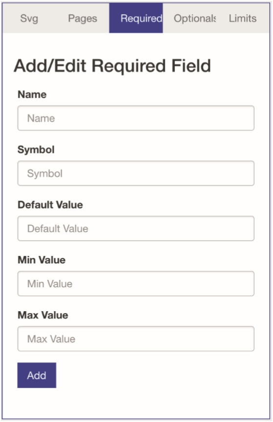
Symbol
The identifier for the respective field to address the corresponding parameter (for example “L“ for the length of the packaging) is determined here.
Default Value
The default value of the respective parameter (e.g. 200 mm for the width of the packaging) is defined here.
Min Value
This field contains the minimum value for the respective parameter.
Max Value
This field contains the maximum value for the respective parameter.
If you want for customers to be able to determine one or several parameters (e.g. length or width) themselves, click “Add” in the web2print settings under “Packaging Variables”.

In order to link the variable with the parameter, you need to enter the designation to be used for the customer in the shop system (e.g. “length”) under “Front Name” and the “Name” from the field in the Packaging Editor under “Code” (e.g. “length”). Here the default values such as length, width and height, which are necessary for the calculation of the box, must be entered.

Once this is set and, as explained above, the option for the creation of user-defined formats has been activated, the option “Own Format” will appear for the customer in the shop system for packaging personalization in the product options.
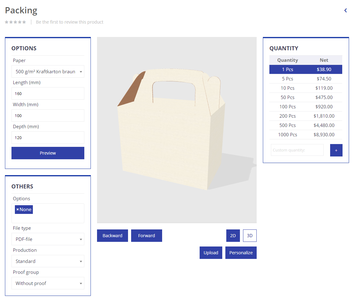
If “Custom Format” is selected, the enabled parameters can be set freely within the defined limits (Min Value and Max Value). If values beyond those limits are entered, a warning message is displayed.
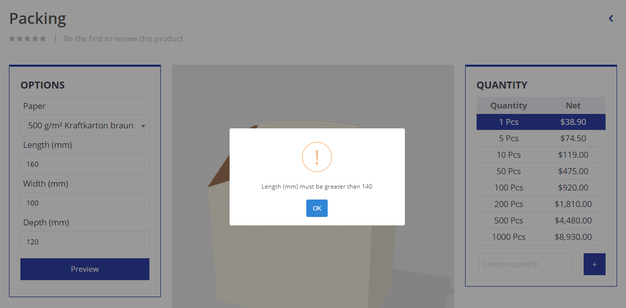
DEFINING RULES
In the Packaging-Editor you can furthermore define packaging configuration rules which, in addition to the maximum and minimum values for the individual parameters, have to be observed by the customer. In order to do so, click “Limits” at the top of the editor menu. You can then define a rule with the following setting options.
Name
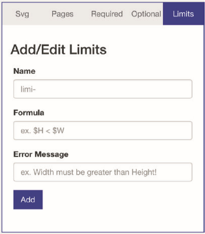
The name for the rule is defined here. It can only be assigned once.
Formula
Here the formula associated with the rule is defined. For this purpose, when using different parameters, their “symbol” value is entered with a dollar sign in front and linked with operators. For example, if you enter “$W > $L”, you define the rule that packagings always have to be wider than they are long.
Error Message
Here you enter an error message which is displayed if the rule is not observed (e.g. “Width must be greater than length.”).
If you want to include a variable within your error message you need to enclose it with curly brackets (e.g. “Width must be greater than {{$L}}.”). You can also include a calculation using a value or variable (e.g. “Width must be greater than {{$L*1.5}}.”)
After clicking “Add” and “Save”, the rule is saved and displayed in the sidebar on the left under “limits”. If you then click “Save” in the upper right, the rule for the model is saved and activated for the customer in the shop system.
OTHER FUNCTIONS OF THE PACKAGING EDITOR
The Packaging Editor has some additional features, the most important of which are the following:
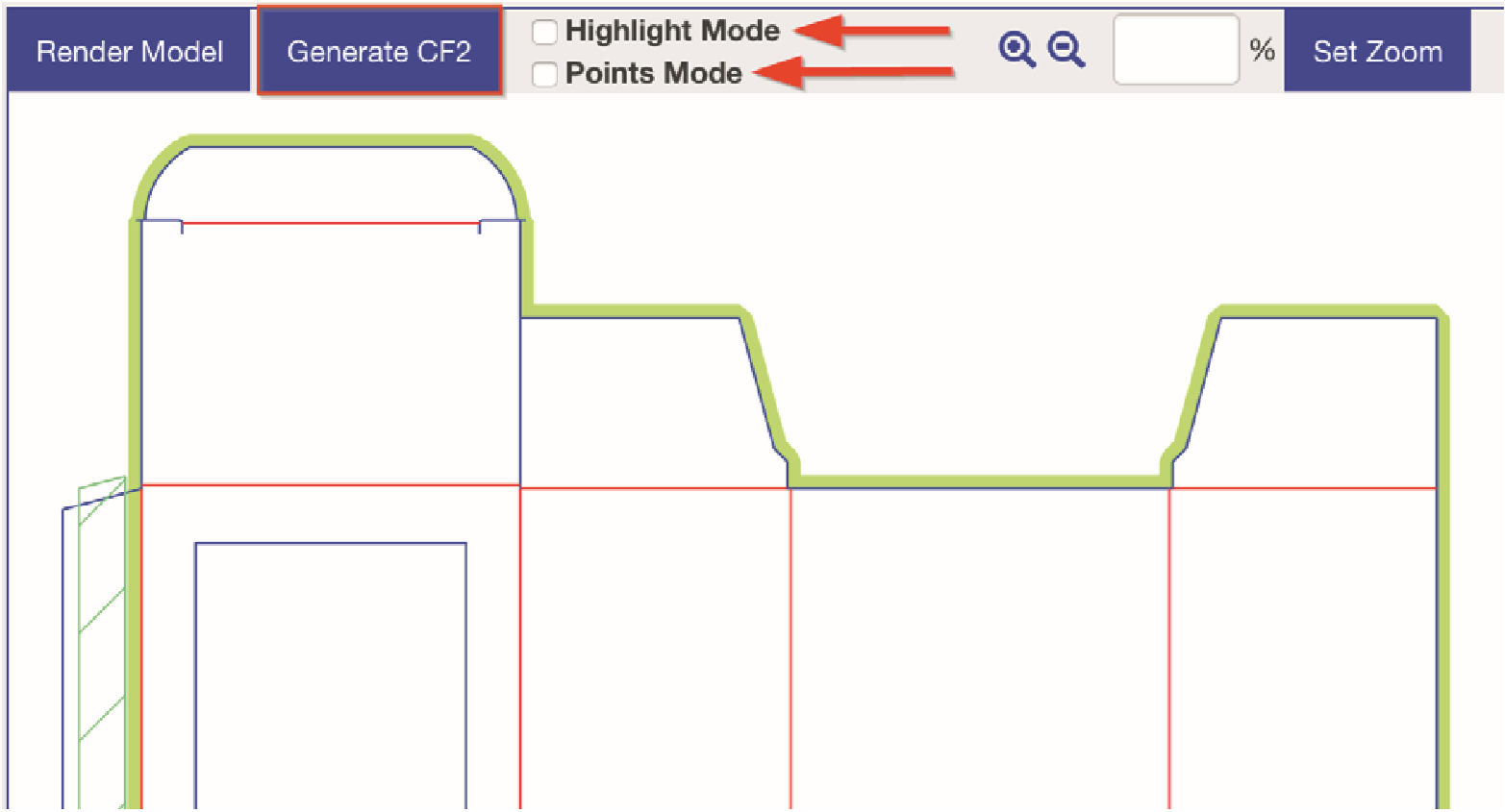
Generate CF2
With this button, a file containing all data for the cutting die of the packaging is generated for download.
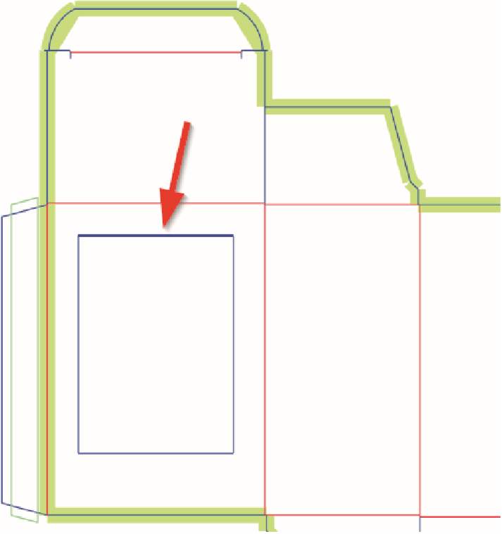
Highlight Mode
If this mode is activated via the check box on the upper right, the system will use colorful highlighting on the model to indicate which part is currently selected in the path list of the model structure on the left.
Points Mode
If this mode is activated via the check box on the upper right and the model is rendered anew via the button “Render Model”, all nodes of the model whose parameters can be changed are displayed. It should be noted here that the nodes are linked to the 3D model. Consequently, in “Point Mode”, three points must always be understood as a compound which creates areas.
