X3 How to reconfigure meshes for packaging models (X3 EN)
In some cases you will find that a packaging model has faulty meshes. They either fold oddly, are seperated from the rest of the model or there is only one mesh where two should be.
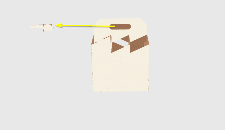
Most issues with incorrect meshes can be solved by manually reconfiguring the meshes, which happens in two steps:
Let’s do this together.
1. Reassign the borders of the meshes
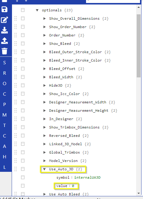
First of all, we have to disable Auto 3D. Go to optionals > Use_Auto_3D and set the value from 1 to 0. This way you disable the automated 3D function and can configure it manually. You won’t see the changes you make until you have disabled this functionality.
After that, if you haven’t done it yet, you will have to add all meshes of a model as described in How to fold packaging models. In our exemplary model, there are 22 meshes, so we have mesh0-21.
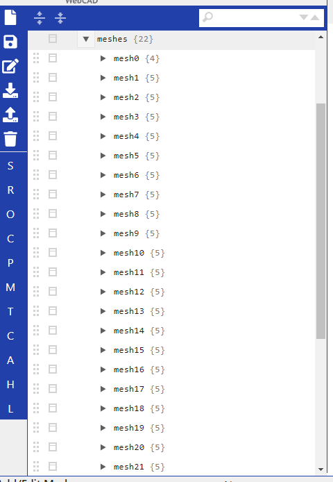
As you can see, the meshes are empty except for the Name:
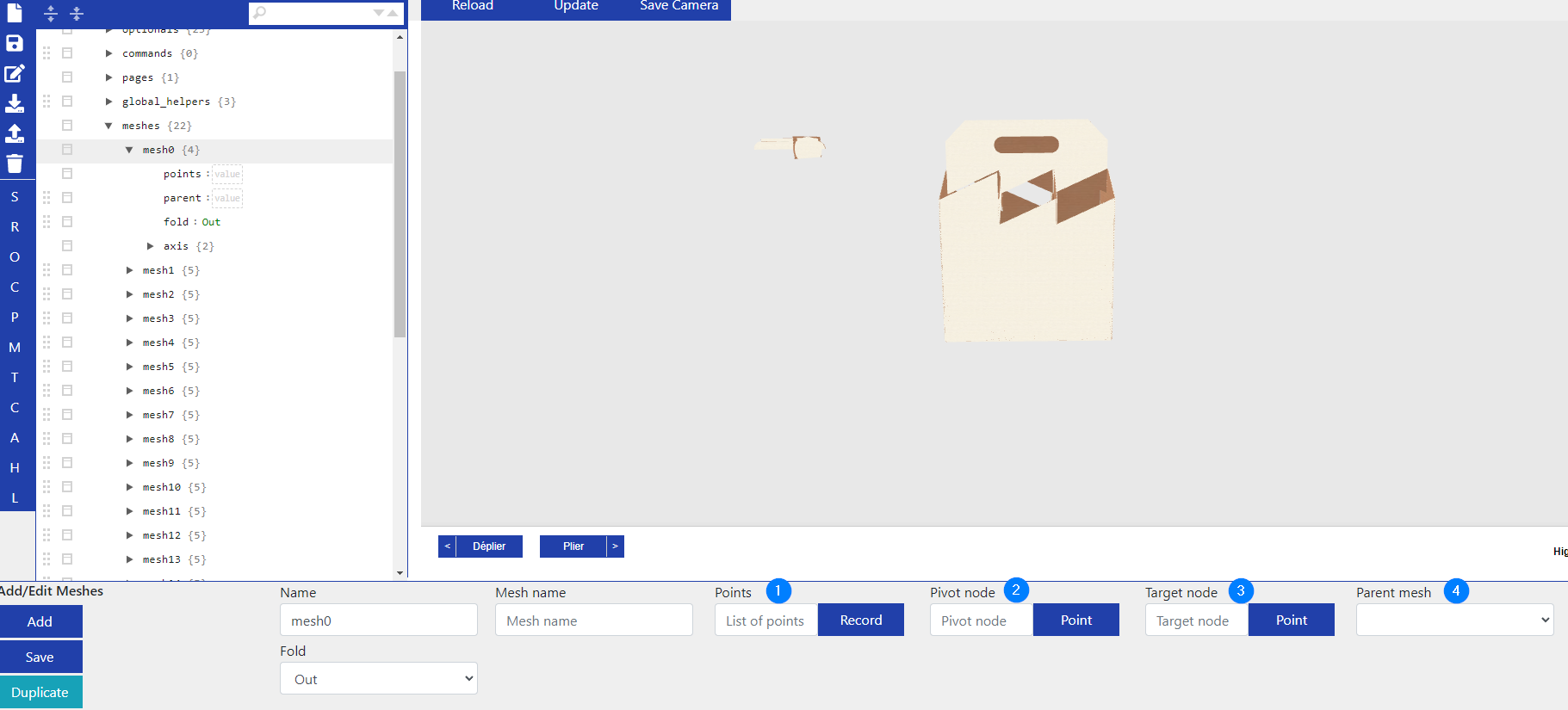
We will add all necessary information by hand, starting with the Points (1), which define the border of a mesh. For this we switch to D3 Rendering at the top and click on Render 3D Model:
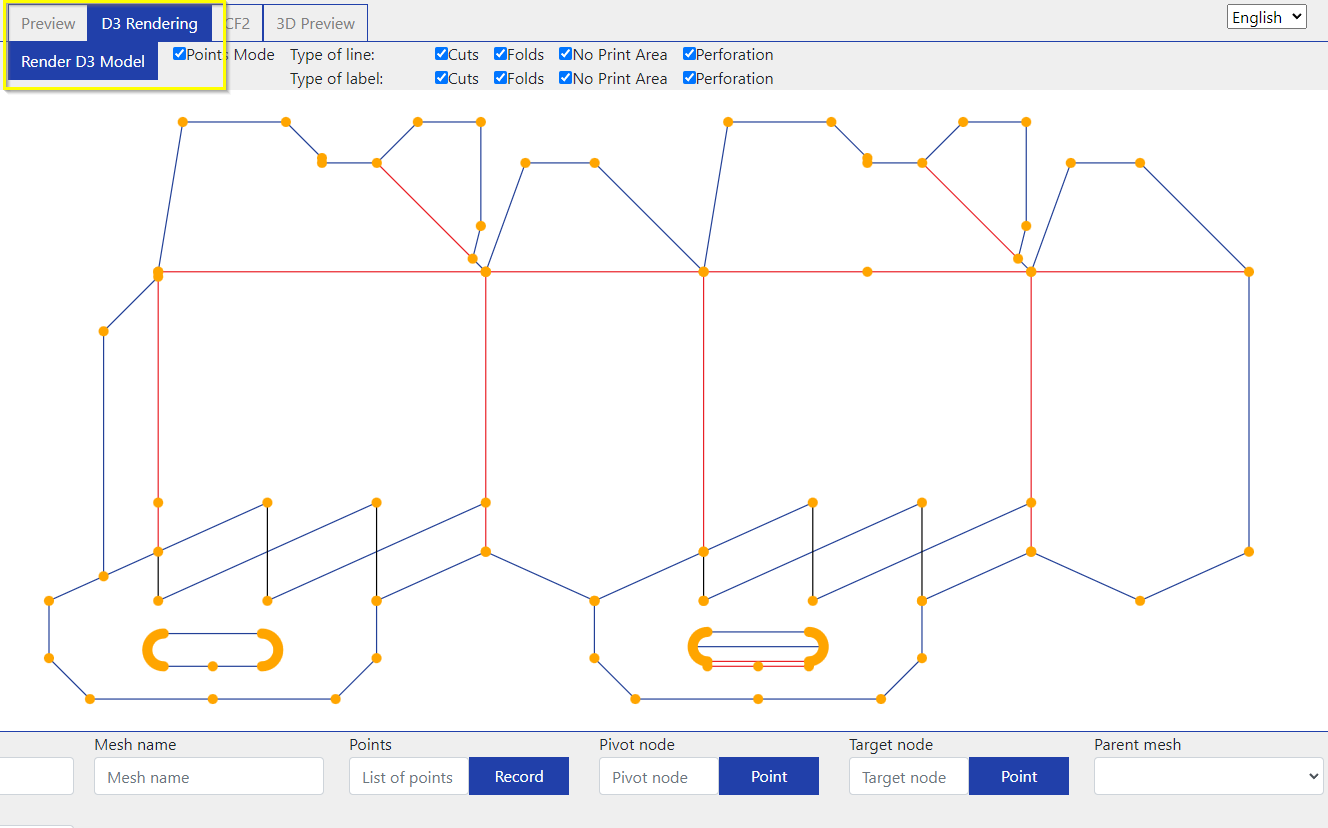
It’s advisable to open a second browser tab where you can check the mesh numbers in the 3D Preview, so you know which mesh number is which mesh. You cannot do it in the D3 rendering, but you need to know which mesh you are working on.
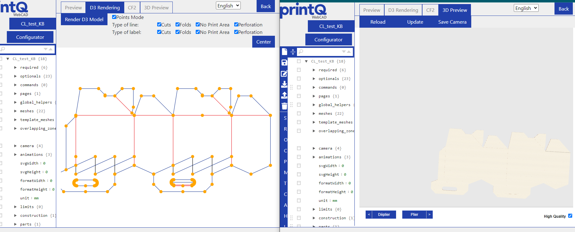
Keep in mind that the D3 rendering displays the model from the outside. You can turn the 3D model until it’s positioned the same way as the rendering to avoid confusion.
We go about this almost the same way as we do when we define Template Meshes. The major difference is, that we have to check all points of the mesh.
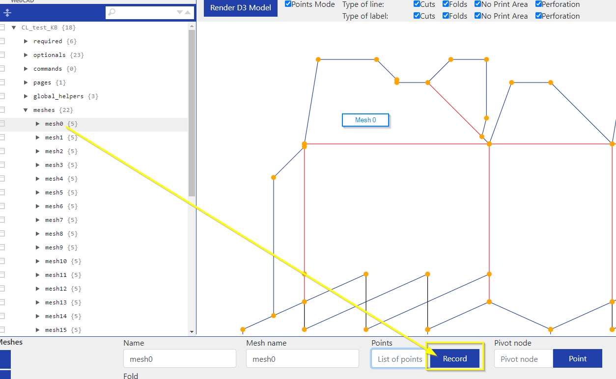
So we check our 3D Preview to find our first mesh, switch to the D3 Rendering and click on mesh0 in the list on the left. Then we can start assigning the borders by clicking on Record:
Select ALL orange points around mesh0 counterclockwise.
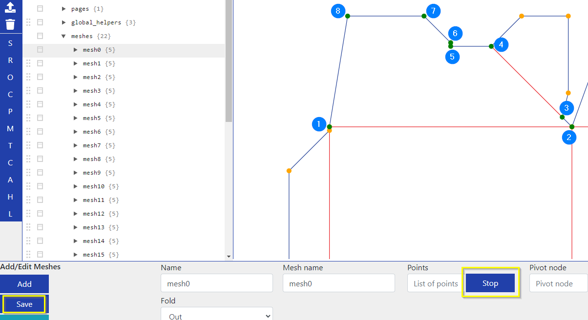
Where we start doesn’t matter, but we have to keep the order of the points and always go counterclockwise. The selected points change color from orange to green. When you are done, click on Stop and then Save the mesh you have adjusted.
(By the way, it doesn’t matter which mesh you start working on, mesh0 or any mesh in-between, just make sure to get all of them.)
This you will have to do for all meshes: Find out the mesh number, record all points counterclockwise and save.
Now some models also have holes. They are a bit trickier to handle, but nothing to worry about.
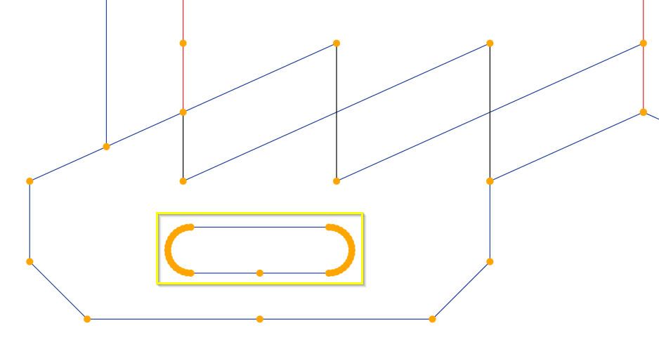
The mesh around the hole is assigned as described above. The hole itself is assigned similarly, but clockwise. It’s done in the same mesh, because the hole is part of that mesh, so you will have to go from the outside contour to the inside one. Let’s call this transition from outside to inside a bridge.
If you assign everything the “normal” way, you will find yourself with a part of the box missing where the bridge connects inside and outside. In this example I have also “forgotten” to select some points to show you what happens to the 3D view if you do this:
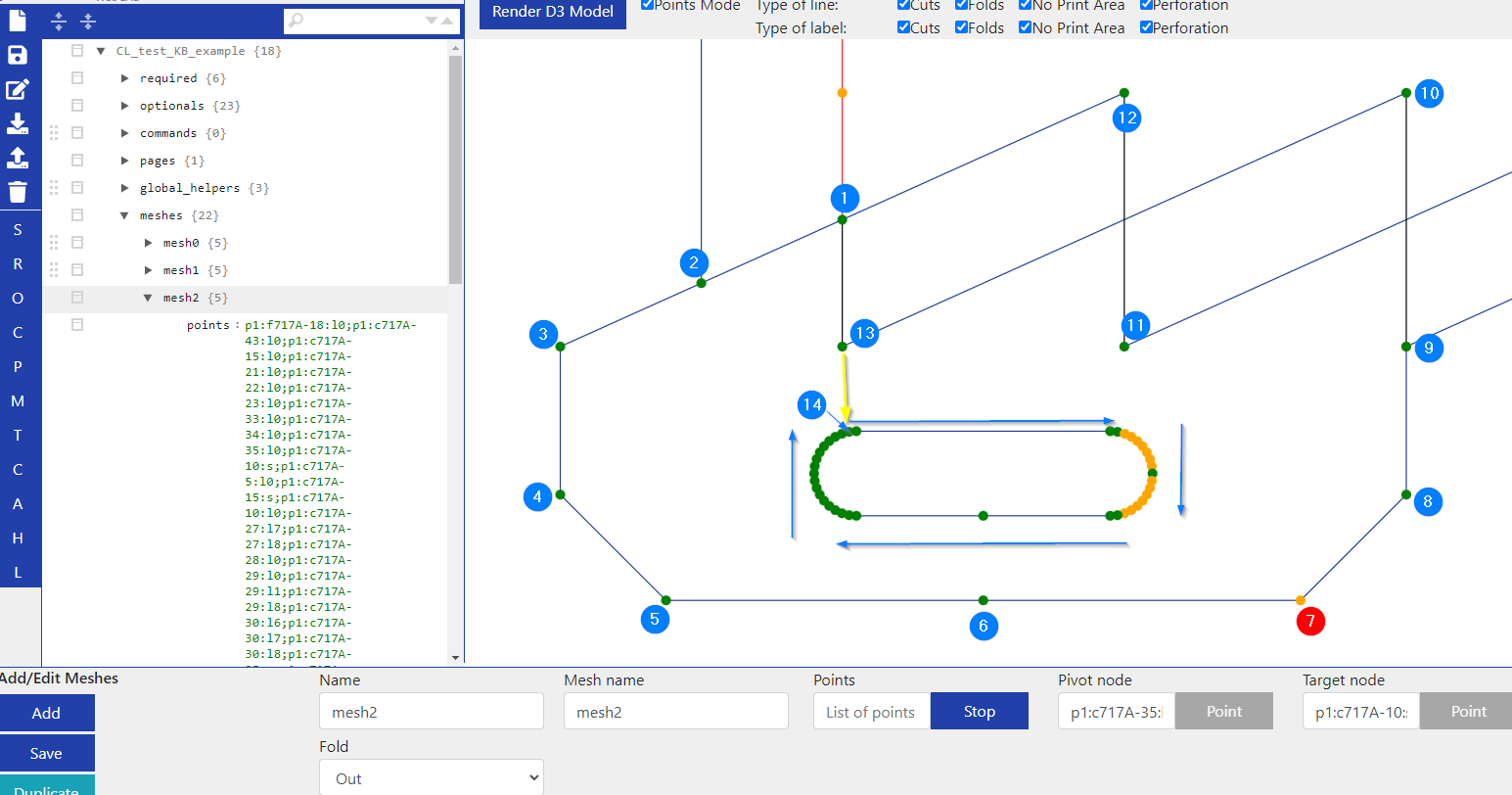
Let’s look at this screenshot. I have started with #1 and gone counterclockwise, but skipped point 7. Then after point 13, I went to the inside contour, the hole and assigned it clockwise, but also skipped several points. The yellow arrow is the transition, our bridge from outside to inside. The result of this selection has several issues:
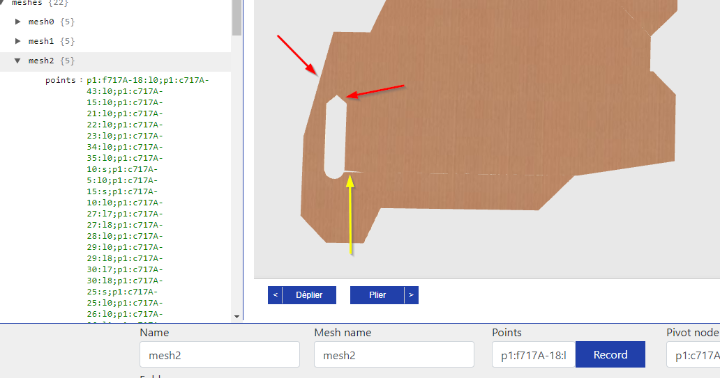
The red arrows show the points we have skipped in our selection. The yellow arrow shows the bridge, where now a little piece of the box is missing.
To avoid the first issue, you just have to make sure to always select all points of a mesh. To avoid the bridge being visible, we have to break our “order” rule and skip one point on the inside contour during our normal clockwise selection.
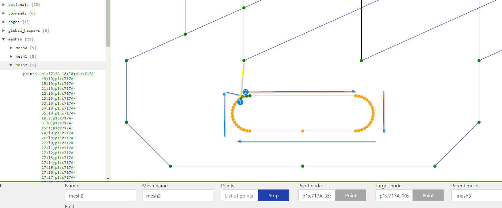
We go from outside to the inside where point #1 gets selected. The point next to it is skipped (clockwise), while all other points after that are selected as usual. Only when we are back to point 1, do we select the point we have previously skipped:
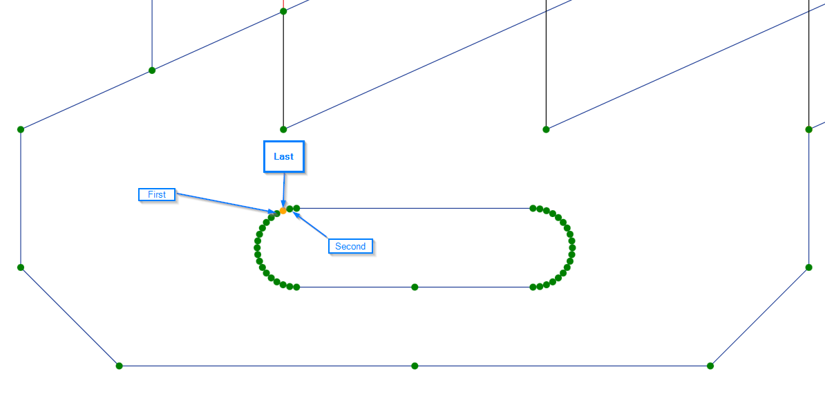
Please remember that all points have to be selected in the end, it’s only the order that is different.
In the end we have a beautiful mesh without cuts and or missing pieces:
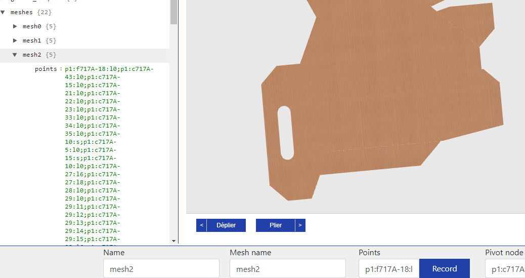
Keep in mind that this specific model has two holes. One might not be seem like a hole because it’s covered by other meshes, but when those meshes get folded away in the 3D, you need a hole to appear where those meshes used to be:
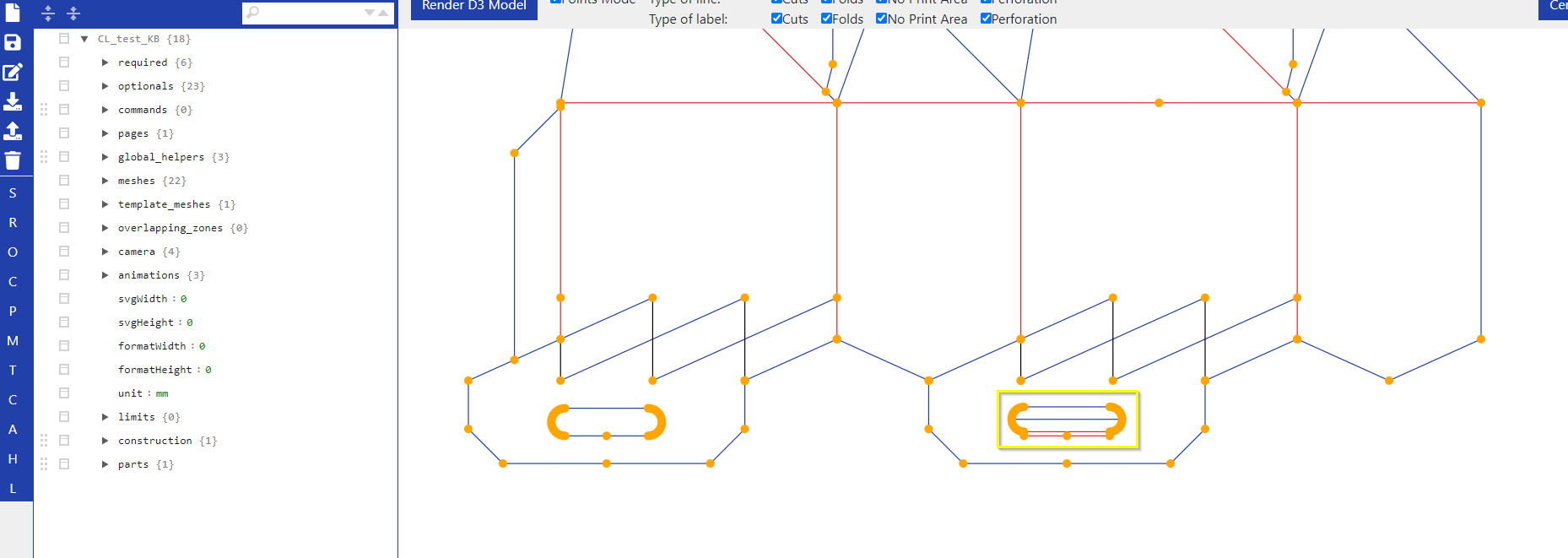
This is basically all you have to know about manual mesh assignment. Let’s talk about the folding.
2. Reassign the folding line and parent mesh
This is relatively straightforward. You go into the mesh you want to fold. Let’s say we want to fold the mesh on the top right to got in the direction of the arrow. Let’s say this is mesh1.
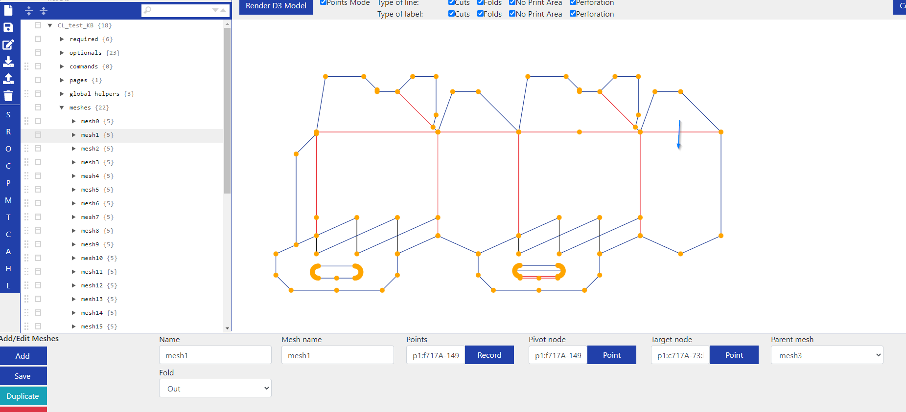
You click on “Point” under Pivot node and select one of the folding points, your selection turns green.
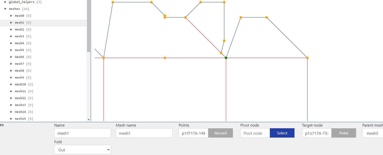
Click on “Select” to confirm your selection.
Do the same with the Target node, which is simply the other point of the folding line.
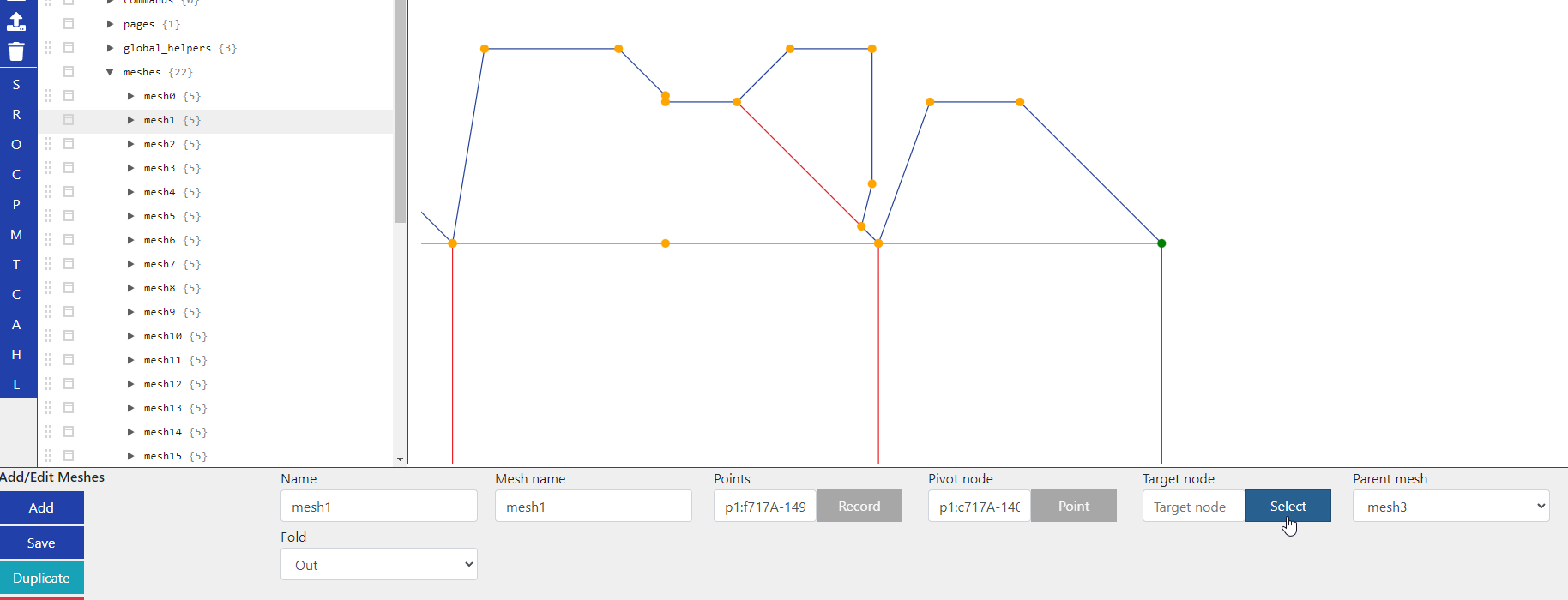
The yellow marked line is now the folding line and the mesh next to it is assigned as the Parent mesh. The mesh we are currently working on will now always fold along the folding line between the two selected points and orientate itself to the parent mesh.
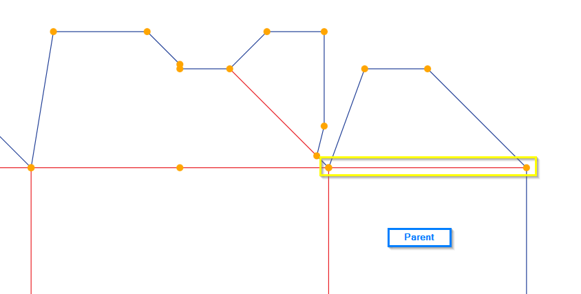
If you have more than two points on a folding line, always select the outermost points. Which one you assign as Pivot and which one as Target node does not matter.
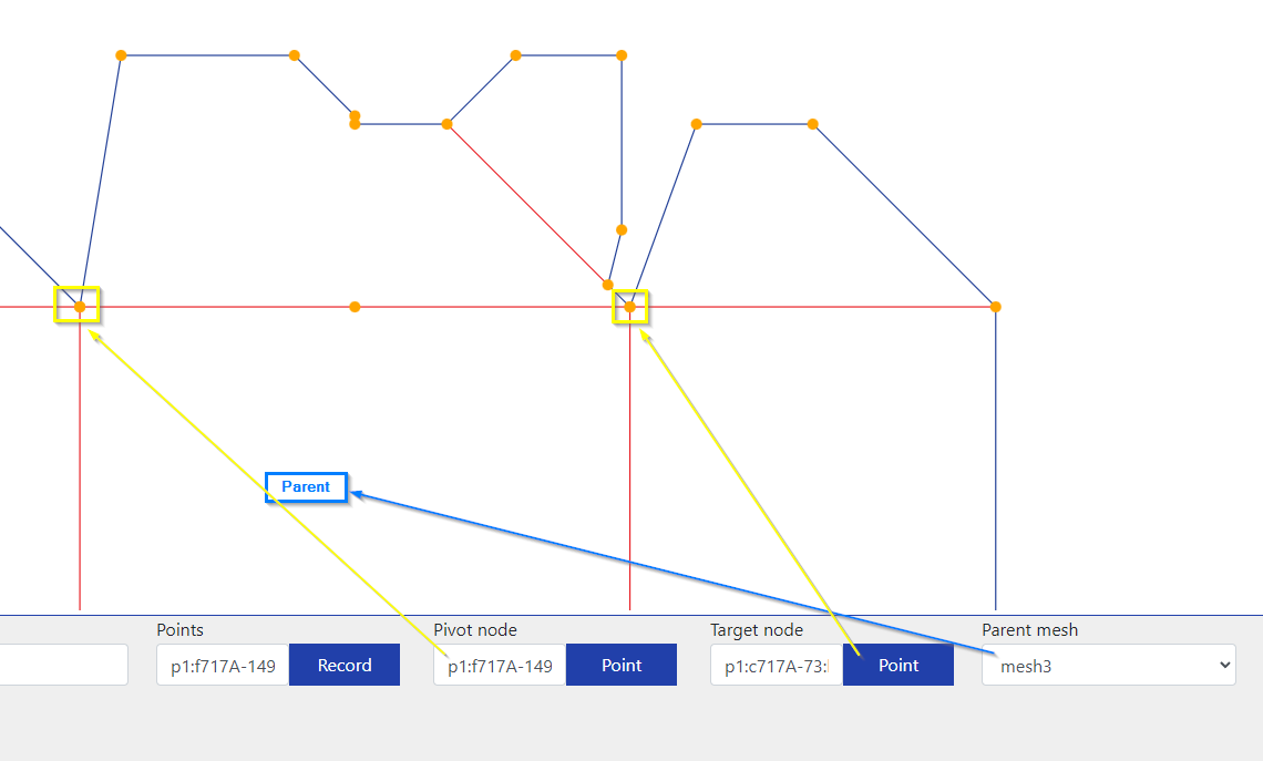
The parent mesh is usually the one going to your “base” mesh, the one you usually don’t fold, because this mesh flips the box instead of just folding itself like the other meshes do.
The blue arrows show an example of the direction in which the folding could happen and thus which parent meshes they could get assigned. The mesh immediately to the left of the base mesh has the base mesh as its parent and would in turn be a suitable parent for the meshes immediately above and to the left of it. The outermost meshes, on the other hand, are rarely suitable as parent meshes.
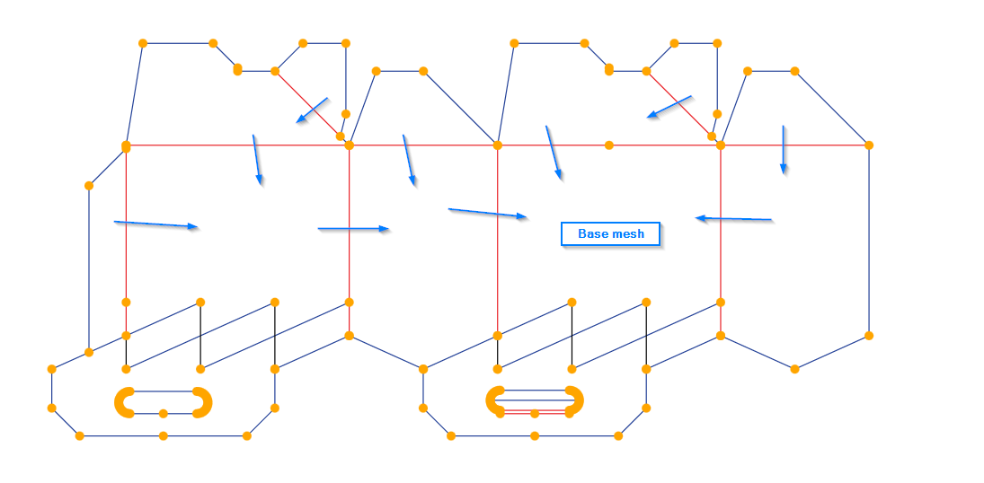
The “base” mesh would be the parent of the three meshes pointing to it. But this is only an example, it’s completely up to you.
Generally you are free to assign any mesh number to any mesh, you don’t have to keep the assignment you initially find in the 3D. We only kept to it to avoid confusion, but it’s not necessary.
And that’s it. Now you know how to manually assign Meshes with their borders, folding lines and parent meshes.
