X3 Packaging Editor (X3 EN)
Configurator
Create a new model
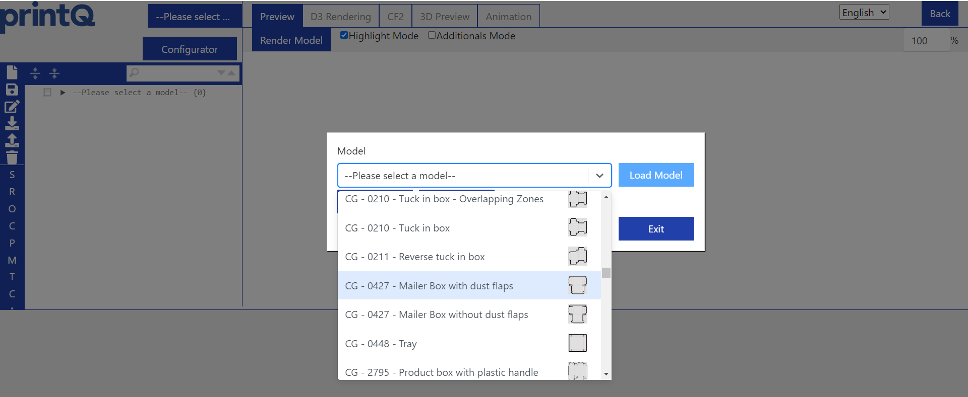
As soon as you click on the packaging editor in the datacenter, you will be redirected to the editor and a selection window will appear.

In this window, you can either select an existing model (1) and load it (2), or you can switch to the configurator (3) to select one of the many models and customize it to your liking.
The X3 system comes with a selection of pre-built models that have been pre-configured by CloudLab to either be used or used as a template for your own customization.
We now want to configure such a model ourselves. To do this, we click on "Configurator" (3).

The new model needs a name. It has nothing to do with the DVS model names, you can freely choose how you want to name your model here.

Once we have decided on a name, we click on Add and are taken to the configurator.
Select a model
Now we see the models that are also listed in the DVS library.
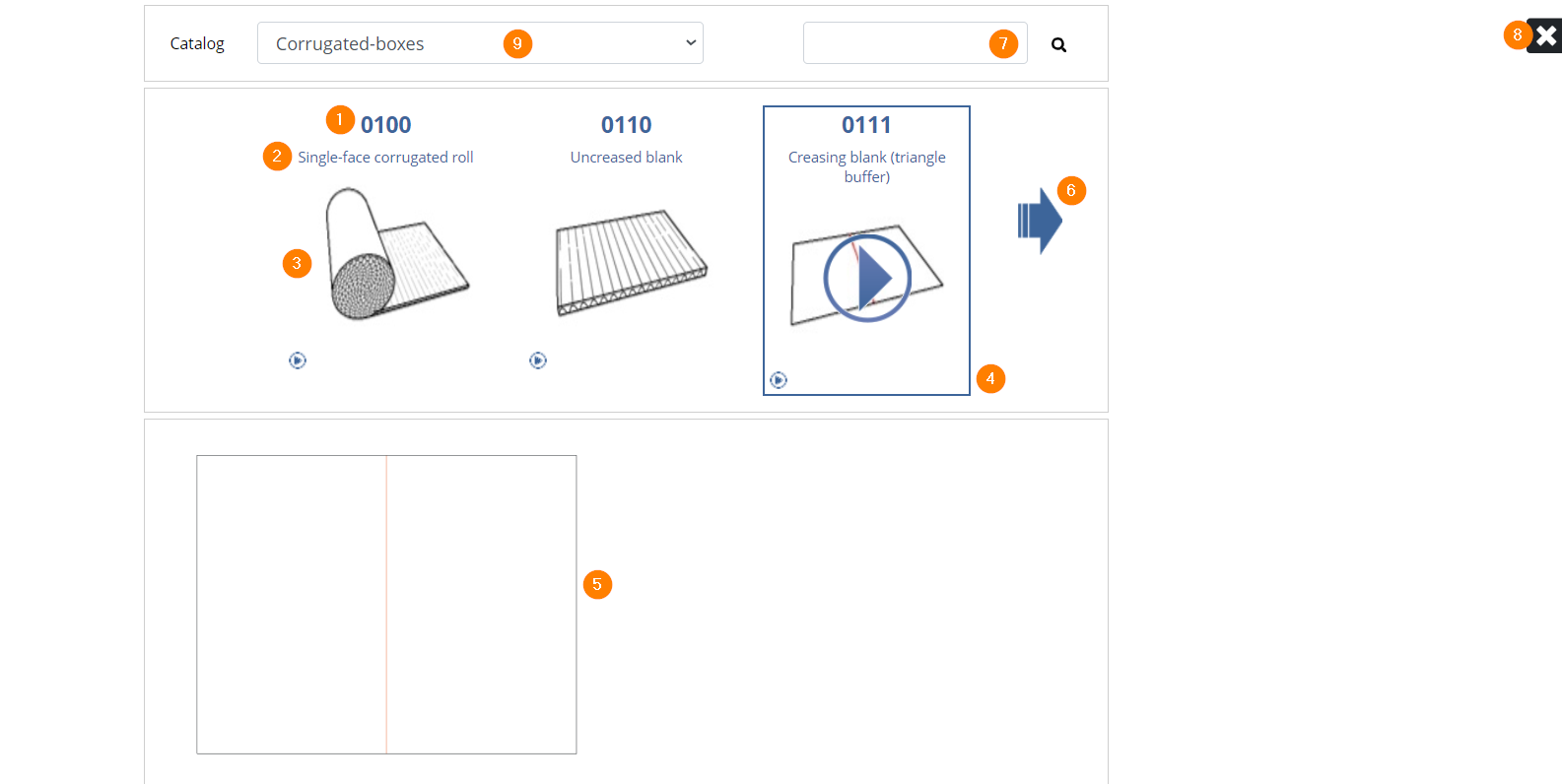
(1) displays the DVS model name again.
(2) is the short description.
(3) shows a picture of the respective model.
(4) shows an image of the respective model.
(5) The frame marks the model that is currently selected.
(6) allows you to scroll through the list. The models are sorted alphabetically and scrolling through such a long list could take a while, so it is best to use (7).
(7) The search function in which you enter the DVS model name to find the desired model immediately.
(8) closes the configurator and takes you back to the editor.
(9) again shows the categories, 3 in English, 3 in German.
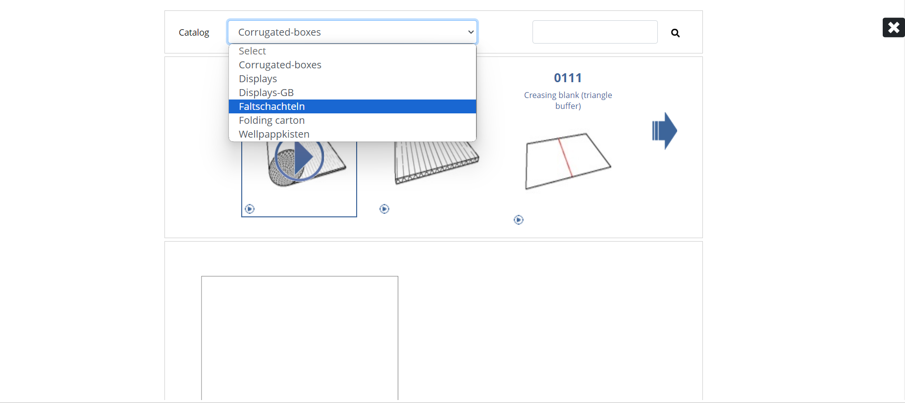
Depending on which category you select, the available models also change.
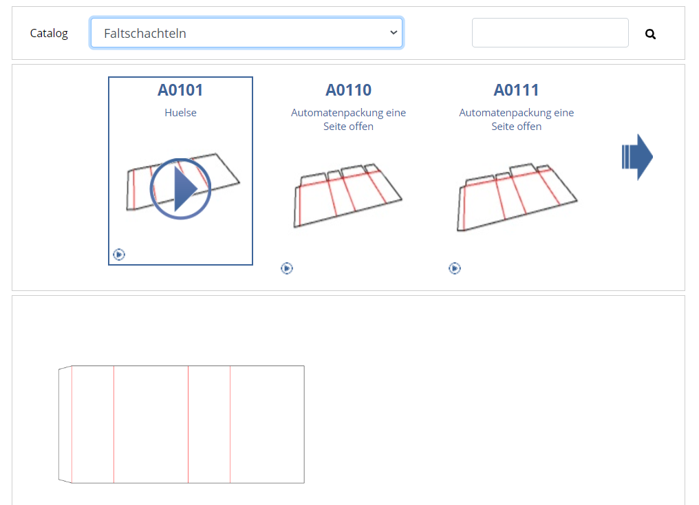
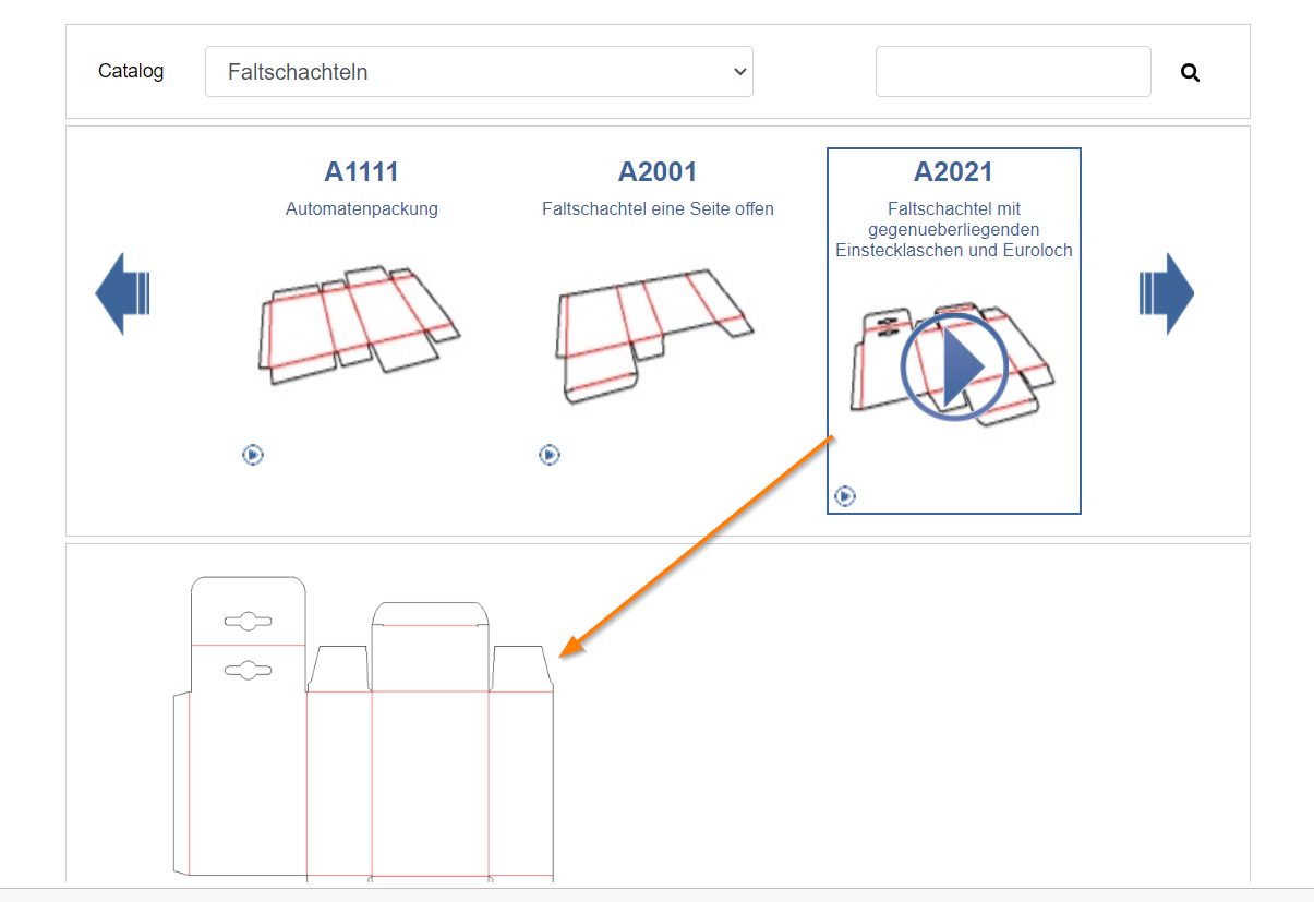
As soon as you click on a model, the 2D standard view of the clicked model appears below it.
Configuring the model
The model options
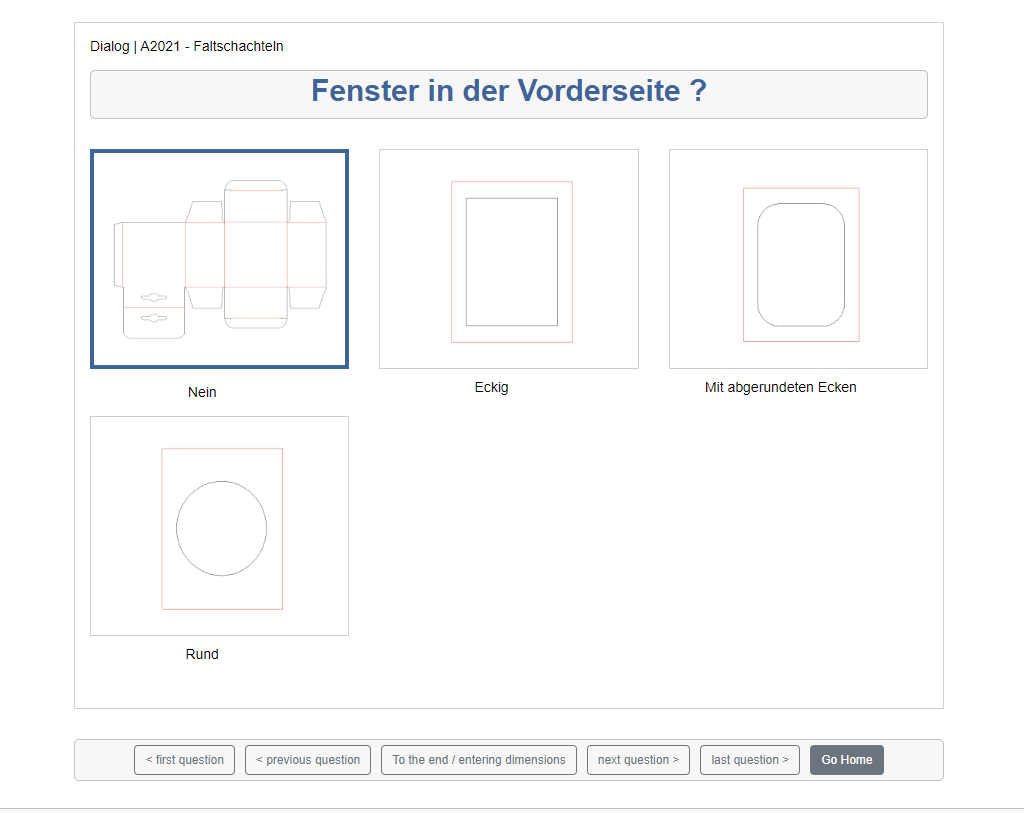
Clicking on the model again selects it and takes you to the options. Each model has different options and a different number of them.
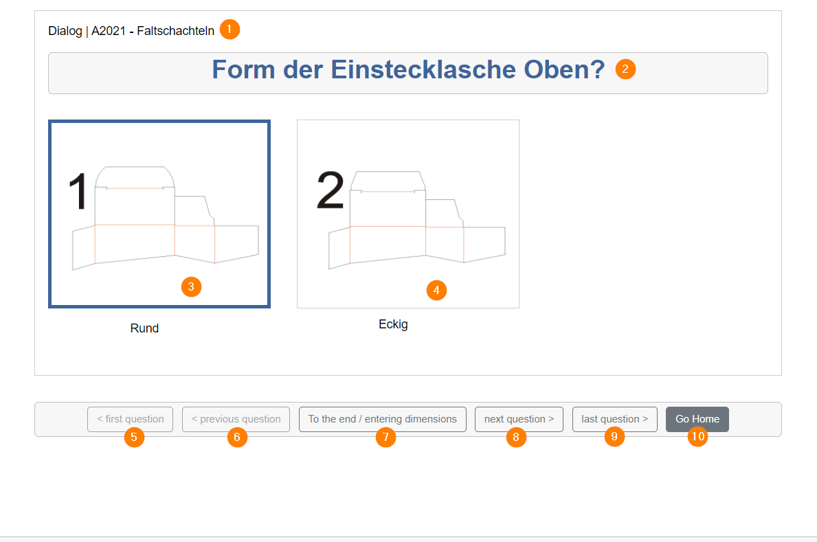
Here is an overview of the first option page of the A2021 model.
(1) shows model name and category (folding boxes).
(2) gives a brief description of the option.
(3) is the selected variant, recognizable by the thicker frame. The first variant is always selected automatically. If you click on it, the selection is confirmed and you are taken to the next option.
(4) is the alternative variant, of which there can be several. If you click on it, it is selected and you are taken to the next option.
(5) If you have already selected several options, you can use this button to jump back to the very first option. If you are already at the first option, nothing happens. In the screenshot, the button is grayed out because we are on page one and jumping back is currently not possible.
(6) scrolls back to the previous option. Here too, you cannot scroll back if you are still at the first option. The button is also grayed out.
(7) skips all questions and goes straight to the last step. As the first variant is always pre-selected, the first variant is always used for all available options if you skip the selection completely. It is not possible for nothing to be selected in an option.
(8) scrolls to the next option.
(9) scrolls to the last option. If you were already at the last option or the model only offers one option, nothing happens.
(10) takes you back to the catalog view where you can select/change your model.
The last step
In the last step, after you have gone through all the options or skipped them, we get to the view where we can enter the dimensions of our model and finish it.
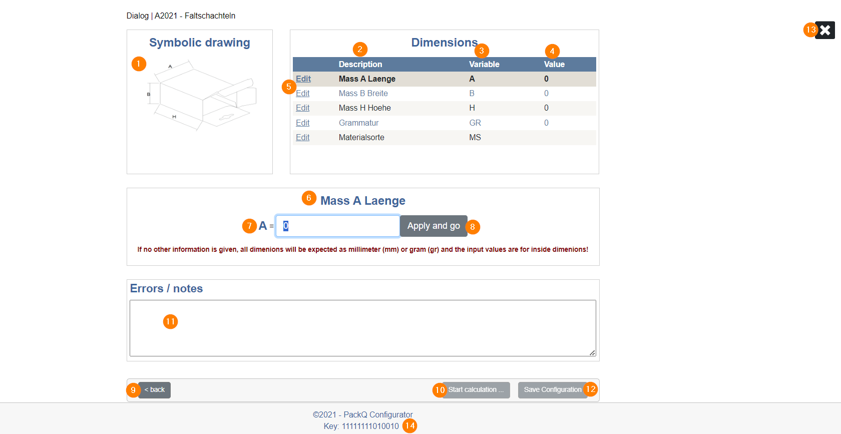
(1) shows a diagram of the model, which shows how the individual variables (here: A, B, H) are assigned to the model and how they will influence it.
(2) is the description of the settings that can be made for this model. This always includes the dimensional variables, which are usually length, width and height. Some models use other variables, in some cases there are more or less than 3. Grammage and material type can be set as desired or left with a default value.
(3) shows the variables that the system actually works with. For length it is usually A, for width B and for height H. For some models, however, there are also other assignments, for example length sometimes has the variable L instead. The variables must not be changed later in the editor.
(4) shows the assigned value. At the beginning it is 0 or empty, and can be entered with (7) and (8), whereupon it is updated at this point.
(5) The Edit button of the respective line takes (7) to the corresponding line so that you can enter the desired value.
(6) indicates which row you are currently in. You can also see this from the grey coloring in the table.
(7) is the input field for the desired values.
(8) logs the value entered in (7) and automatically jumps to the next line in the table.
(9) takes you back to the options.
(10) As soon as all values have been entered and you have pressed button (8) for the last line in the table, this button becomes available and the system calculates whether the values entered are problematic for the model or whether everything fits.
(11) then indicates any issues or confirms that everything is OK and you can continue.
(12) only becomes available after (10) has been clicked. This button saves the configuration, closes the configurator and you are redirected to the Packaging Editor.
(13) You can close the configuration at any time with the X, even during option selection. It is advisable not to cancel the configuration or, if you do, not to save the model and create a new one instead, as otherwise configuration remnants from the first attempt could be retained, which usually does not affect the functionality of the new model created later, but can lead to confusion.
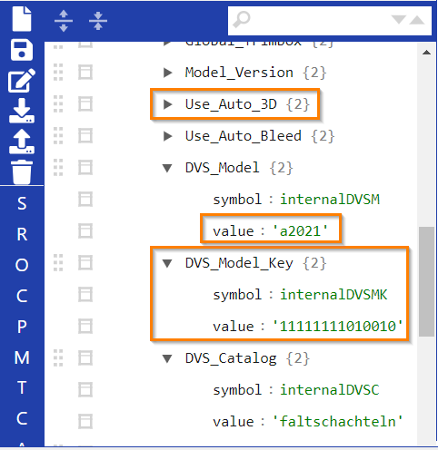
(14) shows the key with which you can identify this model with exactly the configuration you have made. If you select a different variant for one of the options, this will be reflected in the key and it will change. So if you want to reconfigure the model somewhere else at some point, the key can help you to make the exact same configuration.
For corrugated packaging, there are always two additional settings in the last step.
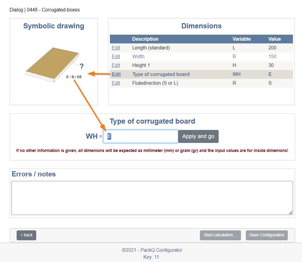
One is the flute or corrugated board type. A recommendation is given directly in the model, so in this case you can enter E, B or EE as the flute type. The flute is the thickness of the corrugated board and can be set in the Page Options.
The other is the orientation of the flute, which can only go in two directions, S and L.
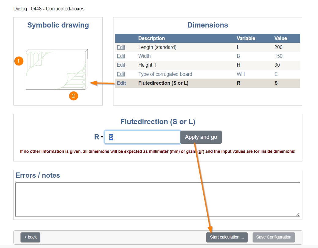
This means that the flute is either horizontal (2) or vertical (1). As soon as you have decided on a version - you can change the selection later - click on "Apply and go". As this is the last setting in the table, clicking this button will activate the "Start calculation" button.
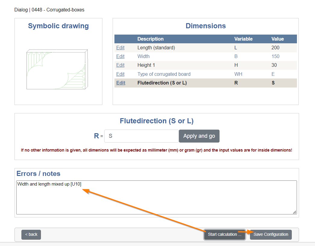
After pressing the button, the system in our example finds something wrong with the settings. Width and length are reversed. The system expects a higher value for the width (150) than for the length (200). It is advisable to correct the noted points so that the model functions correctly.
As soon as you have corrected the noted points, you can log the last line again (Apply and go) and press the button for calculation again.
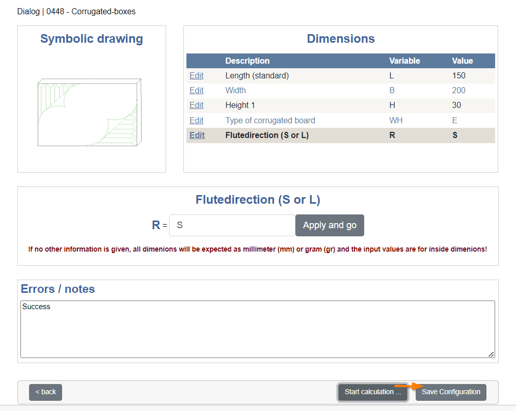
Ideally, the calculation is successful, which the system also informs us of with a "Success" text. The save button is also activated (Save Configuration) so that we can complete the configuration.
This takes us to the Packaging Editor, where we should now save the new model so that it is not lost after closing the editor. Click on the diskette at the top left and your model will be saved.
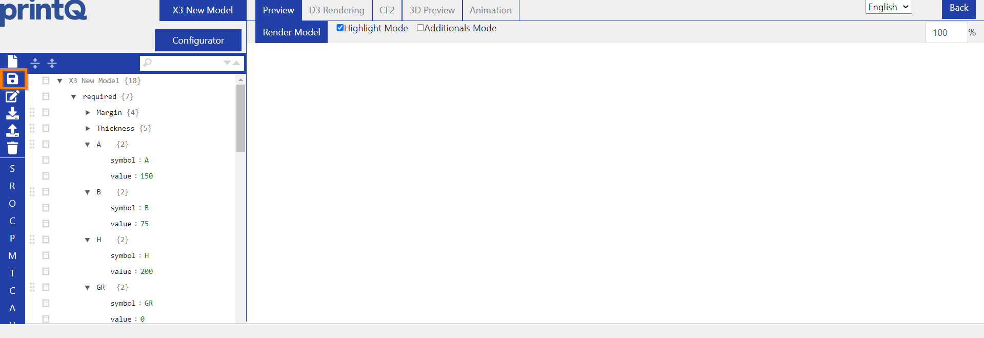
If you want to change an option at a later date, you can return to the configurator from the packaging editor at any time. To do this, click on "Configurator" at the top left and then on "Update Model".
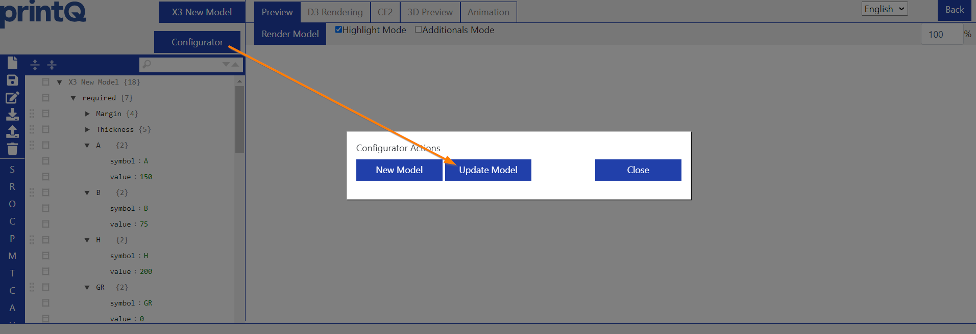
There you can either change your option selection or directly select a completely different model. The latter is not recommended due to the configuration residues mentioned above. For example, if the old model had 4 variables, but you now select one with 3 variables, the 4th variable of the old model remains, even if it has no effect. You can remove it manually from the menu on the left-hand side, but it would be better to create a new model instead of completely replacing an old one.
Packaging Editor
Overview
Once we have loaded an existing model or created a new one in the configurator, we find ourselves in the Packaging Editor.
Navigation
Here is an overview of the basic navigation.
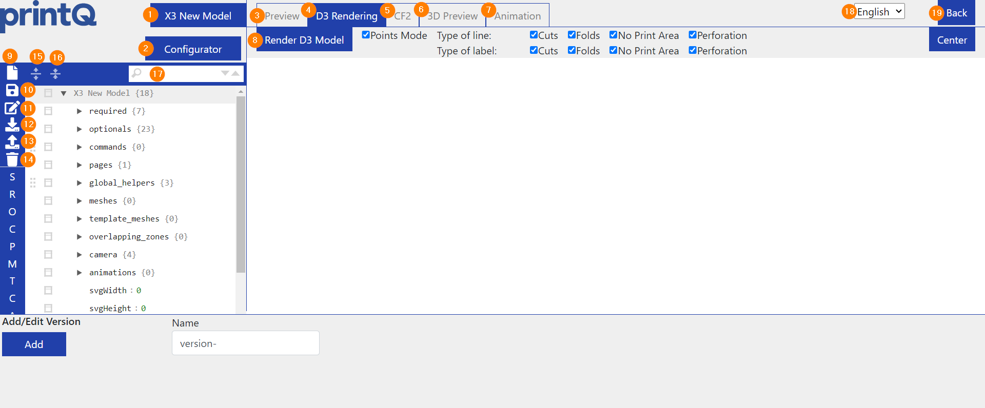
(1) shows the name of the loaded model.
(2) leads to the configurator.
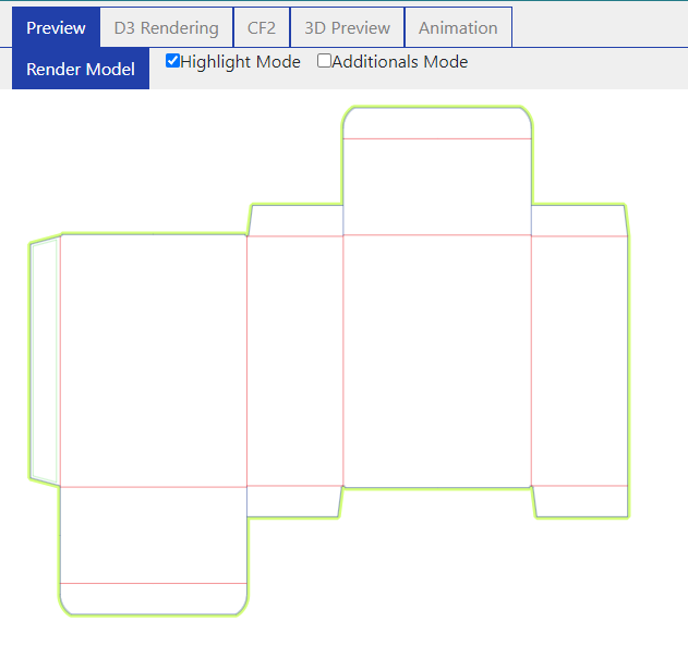
(3) loads a 2D preview of the packaging.
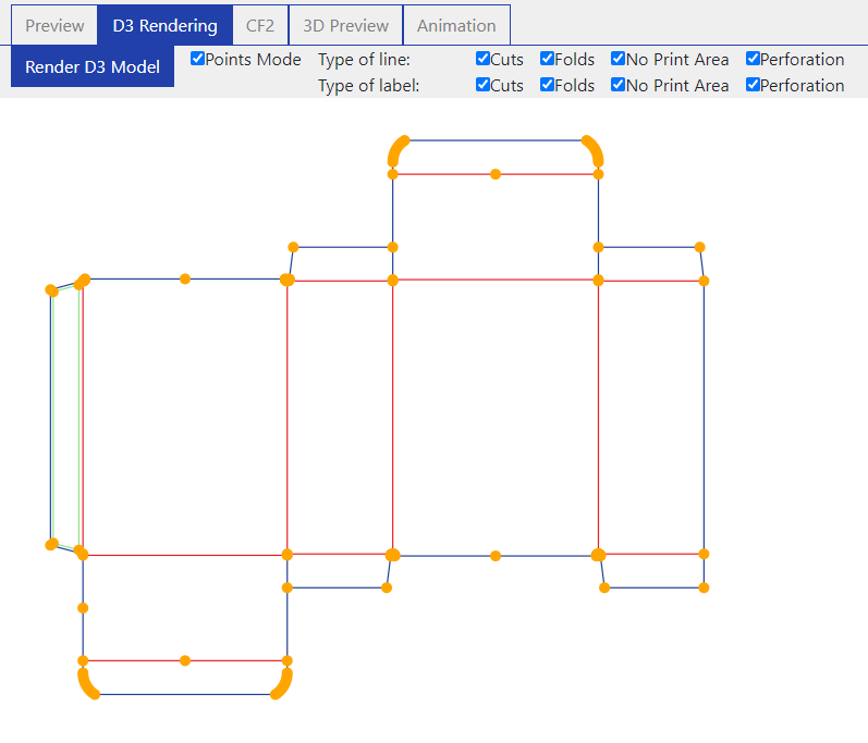
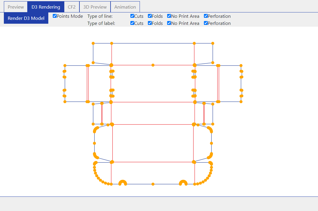
(4) loads the D3 model with nodes. This tab is important for template meshes and overlapping zones, but also for redefining the meshes.
(5) generates a CF2 file.
(6) loads the 3D model.
(7) shows the animation tab
(8) is the button used to load the respective view.
(9) opens a window for creating a new model.
(10) saves the settings of the current model.
(11) is the "Save as" button, which allows you to save the current model under a new name. The original model is retained.
(12) downloads all information of the model in a JSON file.
(13) allows you to upload a JSON file with edited information.
(14) deletes the model.
(15) expands the view of the left table.
(16) collapses the view of the left table.
(17) searches for the entered value in the left table.
(18) changes the language.
(19) closes the editor and returns to the datacenter (only possible if the editor was not opened in a new window, otherwise there is no previous page to return to).
The configuration table
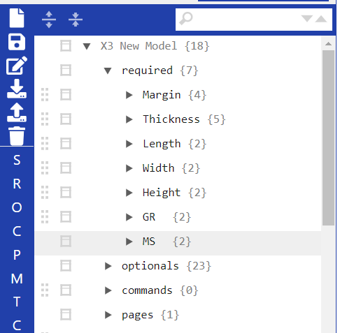
The options for which you might find the most use are listed below.
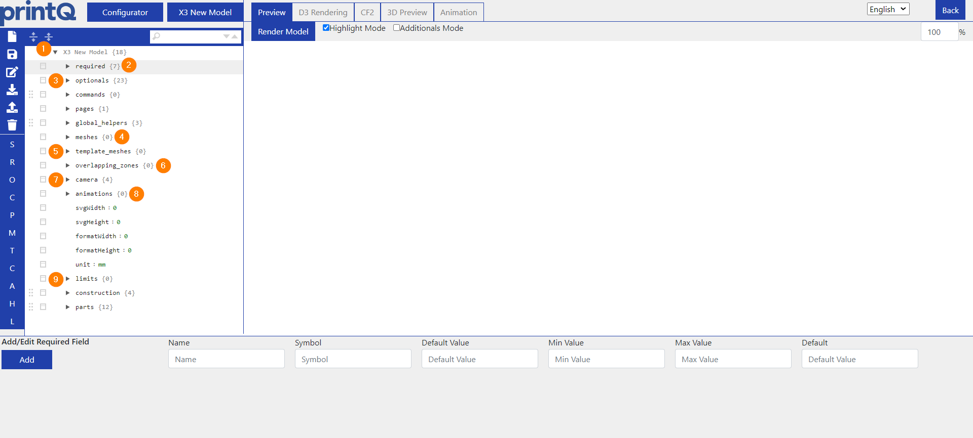
(1) Here you can see the name of your packaging model again.
(2) Required contains the variables you have already learned in the configurator for the dimensions of the model or the corrugated cardboard settings, if it is a corrugated cardboard model.
Various settings can be viewed and additional settings can be made under Optionals. Here you will find the configuration key and other information.
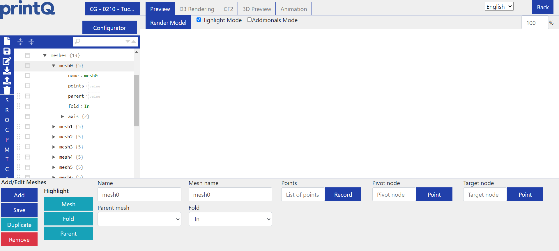
(4) You can enter the meshes here if you want to adjust the folding of your model manually. You can find more on this topic here: How to fold packaging models
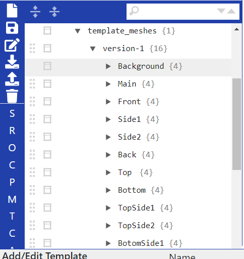
(5) Under template meshes, you can configure your model so that the designs of the Template Gallery are applied to it correctly.
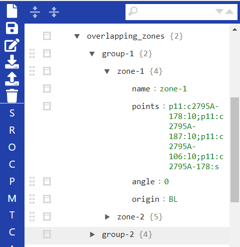
(6) You can read more about the overlapping zones here: Overlapping Zones for Packaging
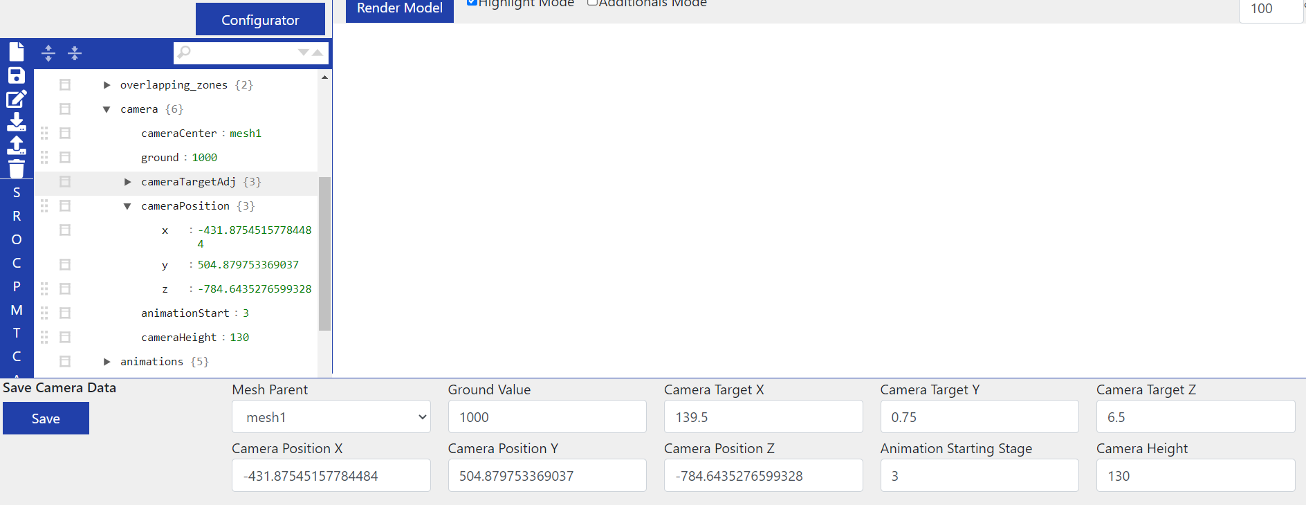
(7) Under Camera, you can specify the position of the 3D model. This ensures that the 3D model is always loaded in the position you have specified.
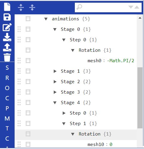
(8) When creating a model, the folding of the 3D is always generated automatically, but you can manually adjust it in Animations.
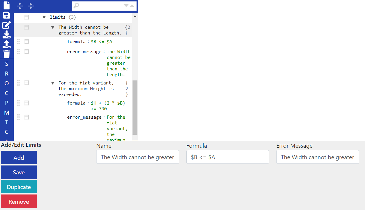
(9) Under Limits, you can set restrictions for the dimensions of your model in relation to the other dimensions. For example, the width may not be greater than half the height.
Variables
Variables in the Packaging Editor
The first thing you should do after successfully creating a model is to rename the measurement variables to avoid confusion later on, as they are currently called A, B and H.
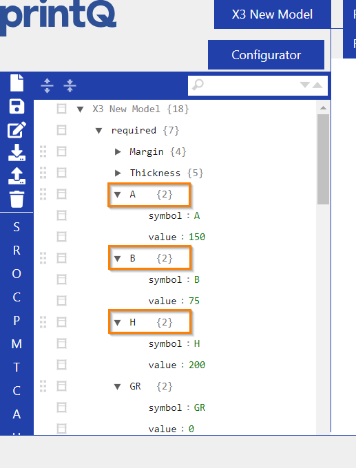
It is very important to only change the names of the variables, not the symbols directly underneath, as these must remain as they are, otherwise errors will occur.
However, the names cannot be changed arbitrarily either, but must conform to fixed naming conventions, which are as follows in all languages: Length, Width, Height.
If different names are chosen or a typo creeps in, the value of the corresponding variable cannot be changed later in the frontend because the system does not recognize that this variable is being referred to due to a different spelling.
The other variables can be left as they are, as we only need the dimension variables for the frontend and renaming them is therefore important.
If you change your mind about the values entered in the configurator earlier, you can change them directly in the variables.
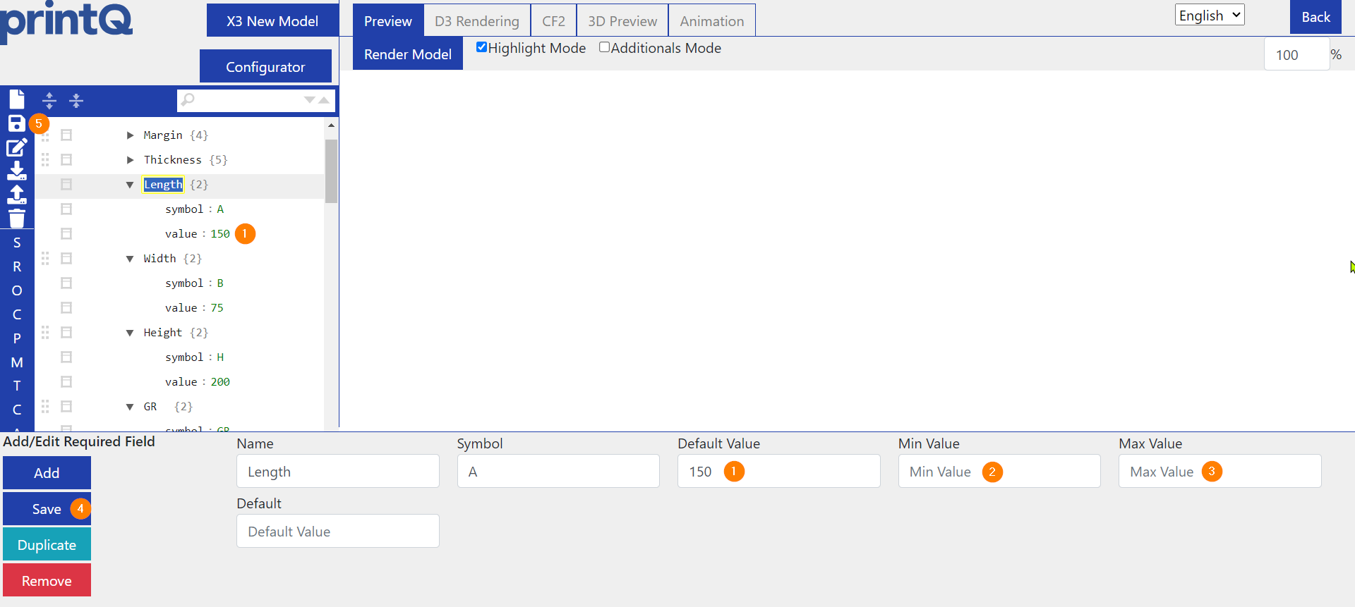
(1) is the default value.
(2) shows a minimum value that you can leave blank or specify yourself. If a customer enters a value in the frontend that is below the minimum value you have entered, they will receive a message informing them that their value must not be below this number.
(3) The same applies to the maximum value. Formulas similar to those used for the limits can also be entered instead of fixed figures.
(4) It is important that you save your changes with "Save" after each change at the bottom.
(5) Use the diskette to save all changes that have been made in the model.
Also worth mentioning is the variable Thickness. It determines the thickness of the carton, which is relevant for corrugated packaging because it reflects the selected flute.
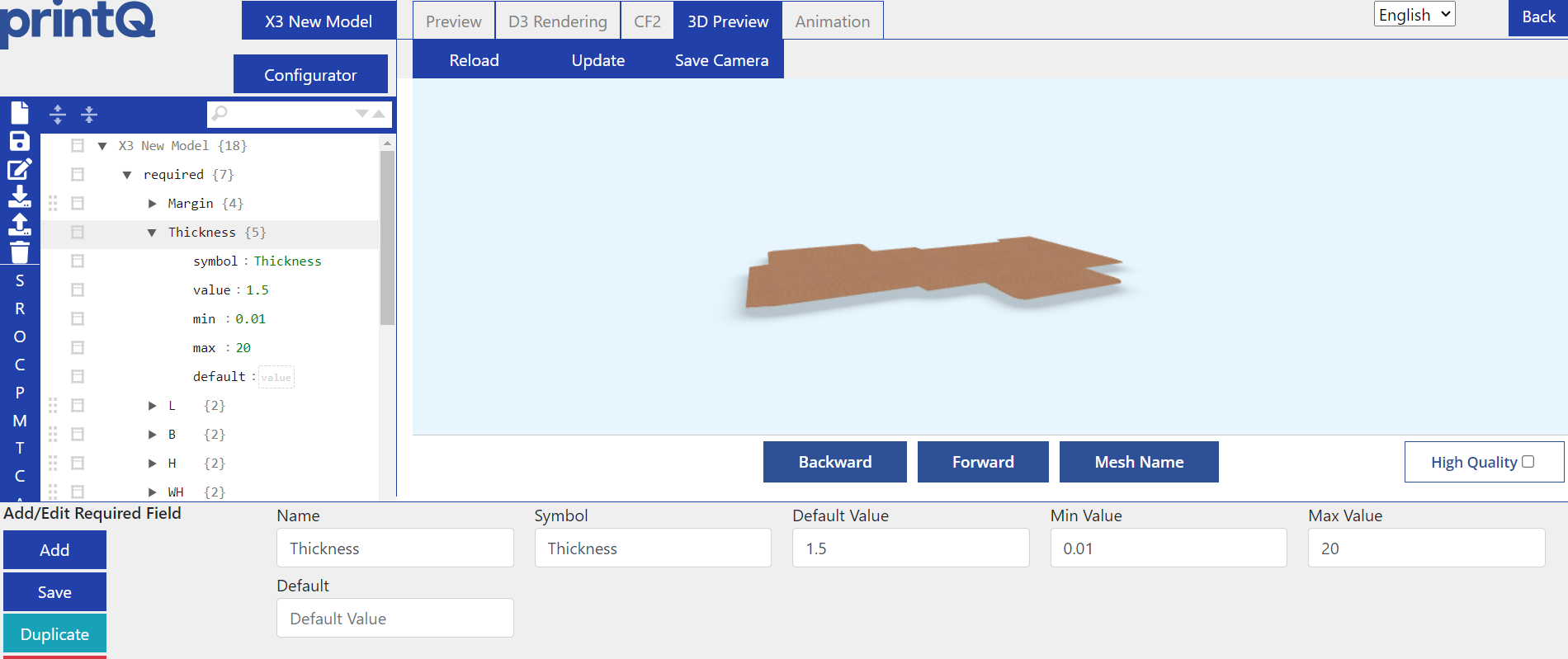
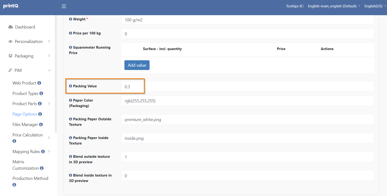
However, the variables are only really decisive for the packaging editor, as the final thickness and dimensions of the frontend packaging are determined by the format and paper/material. The format specifies the actual size of the packaging, which can deviate from the dimensions in the packaging editor, but ideally should not, because you have to prepare the 3D model for the frontend in the editor. The same applies to the thickness, which is determined in the material, namely in the packing value of the respective paper.
Variables in the web product
In the web product you need to select Packaging as the Type to be able to use packaging models in your product.

Below you can select your packaging model and enter the variable names that correspond to those of the model in the packaging editor.
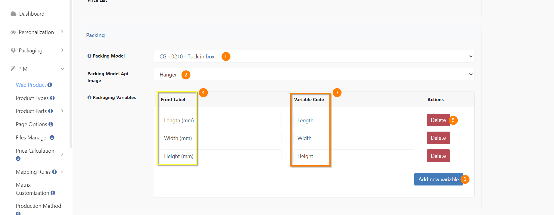
(1) Here you can select your finished model from the Packaging Editor.
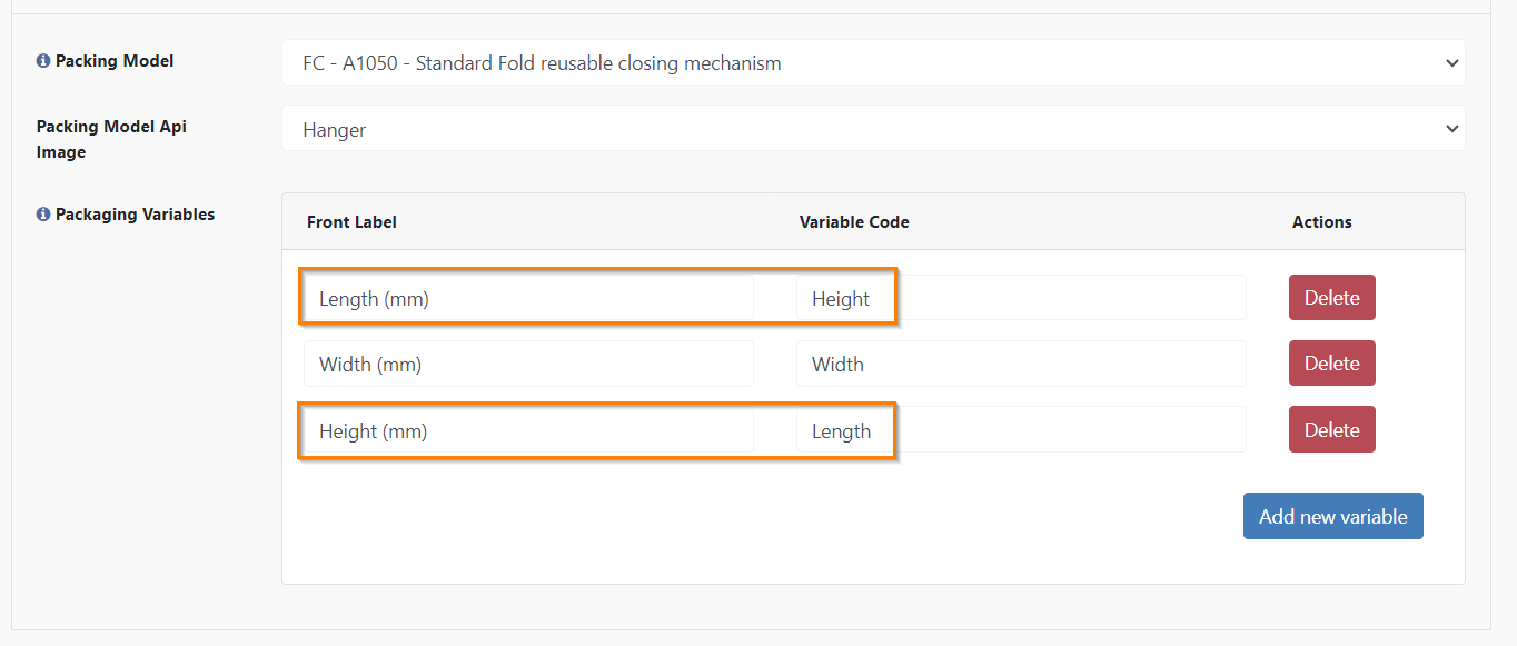
(2) sets which view the Template Gallery designs should have in the editor. The default view is "Hanger", but there are a few other variants.
(3) displays the variable names. They must correspond exactly to those of the Packaging Editor.
(4) Here you can enter how the variables from the orange square should be displayed in the frontend. You can add a unit of measurement, translate the names or leave them as they are. For some models, it even makes sense to swap names so that, for example, the length looks like the height to the customer, e.g. if the model is lying on its side and the height goes from left to right instead of from bottom to top. As this could confuse the customer, the variable that goes from bottom to top is declared as the height, although it is actually the length.
(5) deletes a line.
(6) adds a line. When creating a new web product, there are initially no lines. They must first be added with this button. If a dimension variable is not inserted, it will not appear in the frontend. This means, for example, that if you have a product with variable length and width but a fixed height, you can simply omit the height variable and the customer will not be able to adjust it.
Variables in the frontend
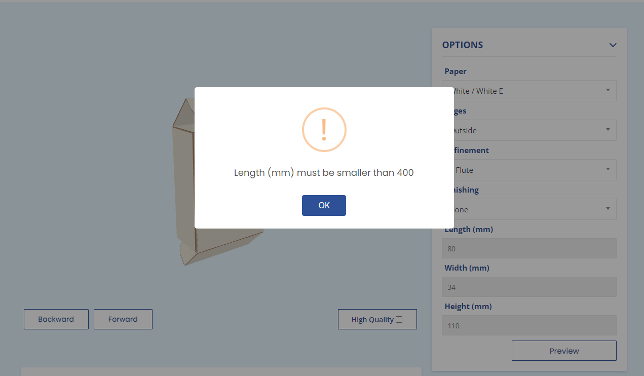
Here is an example of the message that you receive if you enter a value for length that exceeds the maximum value. The messages can be translated in the datacenter or on the FTP server.
And here is an example of the height falling below the minimum value.
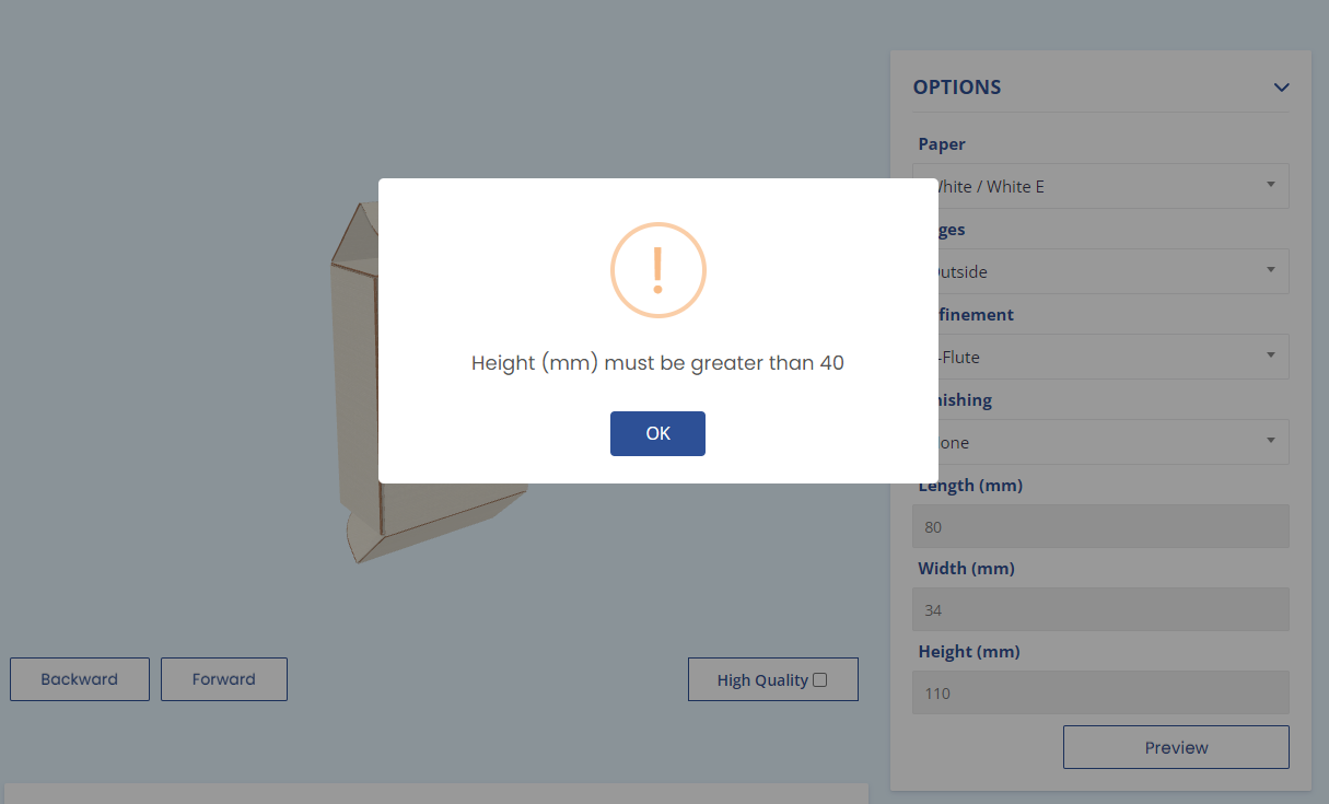
If a forbidden value is entered, it always jumps back to the previous, valid value. The 30 that was entered for Height immediately jumped back to 110 because values below 40 are not permitted.
Additional variables under optionals
There are three additional variables that are not normally present in the models and are not required, but are briefly presented here in case you would like to configure your model further. All three variables may only be added under optionals as new fields.
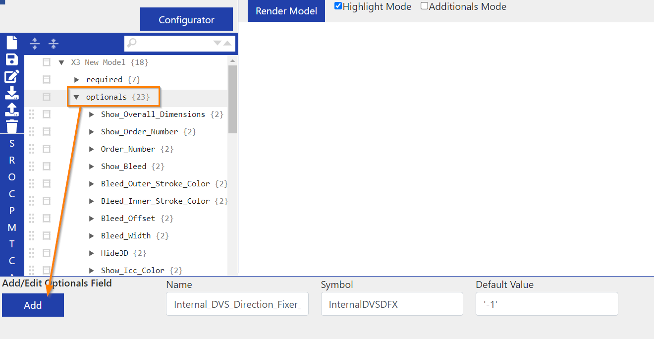
First, we have the variable that mirrors the 2D model along the X-axis.
Name: Internal_DVS_Direction_Fixer_X
Code: InternalDVSDFX
Default value: '1'
Mirroring value: '-1'
Then, of course, there is also a variable that mirrors the 2D model along the Y-axis.
Name: Internal_DVS_Direction_Fixer_Y
Code: InternalDVSDFY
Default value: '1'
Mirroring value: '-1'
So if you want to flip the 2D, you can use one of these variables. However, it is not advisable to do this if you already have a fully configured model, because you would have to adjust the folding, template meshes, etc., as their foundation will be flipped. There are some models where the 2D is upside down, but this is usually because the model makes sense as a folded box and the customer would place the designs the wrong way round if the model was the right way up.
The third variable is used to set a new base mesh for the 3D model and must be added again under optionals. All variables are always case-sensitive and a typing error will result in the variable not working.
Name: Master_Parent
Code: internalMP_3D
Value: one of the available mesh numbers, i.e. '0' to ...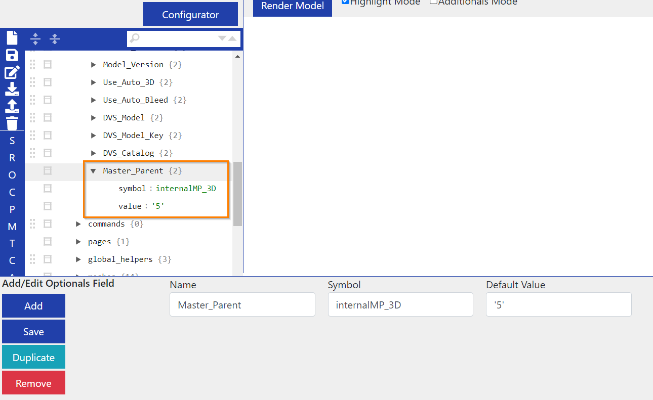
As a rule, you only need the additional variables if you want to manually adjust your 3D model beyond simple folding. If you place the box on its side or upside down, for example, the centre of rotation will change and the movements of the box may feel strange. To fix this, you can make either the (new) base or the (new) back of the box the base mesh, which will make the rotation feel more natural again.
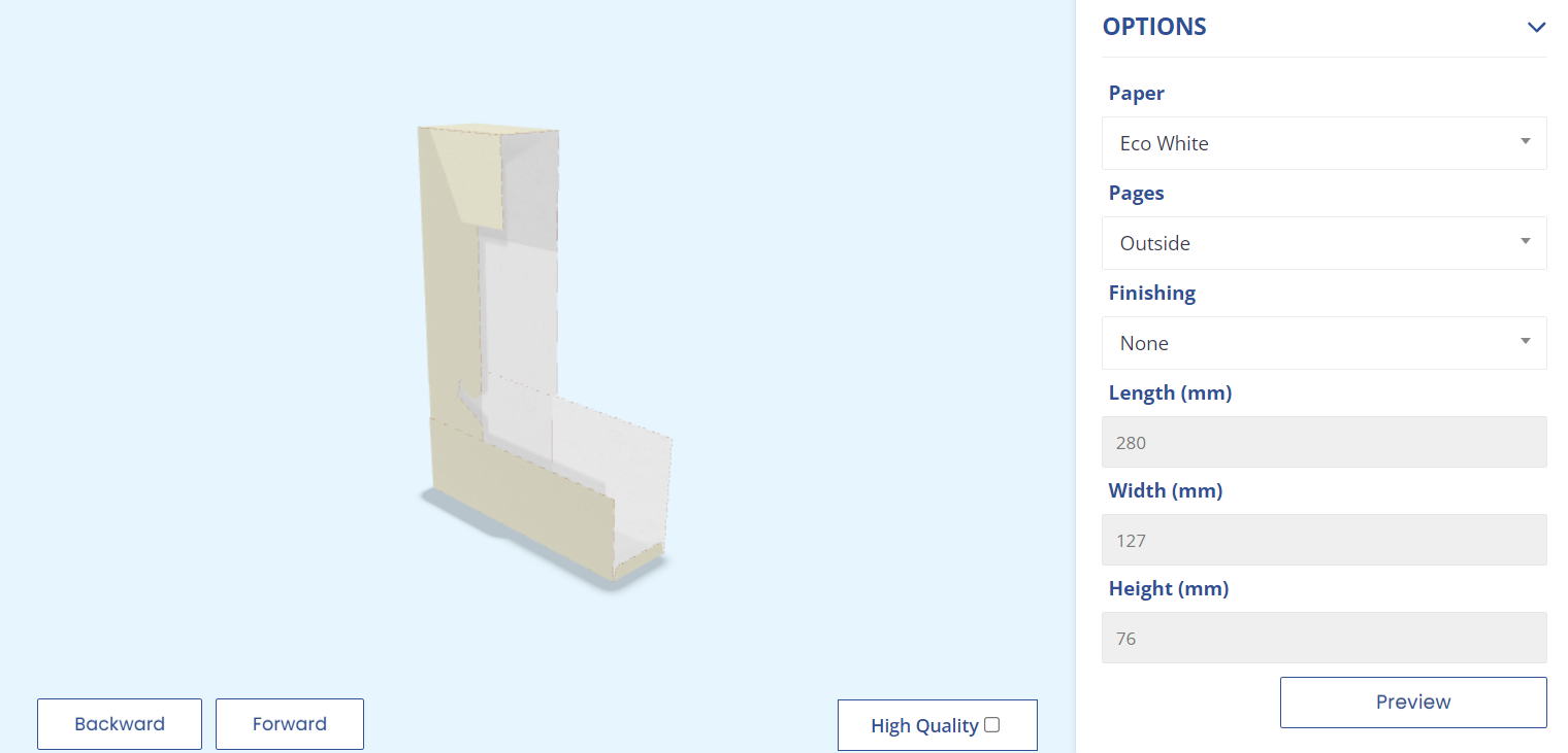
Such boxes are already preconfigured on the X3 systems so that you can use them as an example. The Standard Fold reusable closing mechanism is one of them. The box is on its side and the base mesh was originally 6. We have changed it to 0 and now mesh 0 is the new base of the box. So originally it was standing on mesh 6, now it is standing on mesh 0 because we have added the variable and entered the value '0'.
Limits
In addition to minimum and maximum values, the dimensions of a model can also be restricted using limits. The difference is that you don't just enter fixed numbers for the limits, but formulas that calculate the sides in relation to each other and prohibit certain over- or underruns.
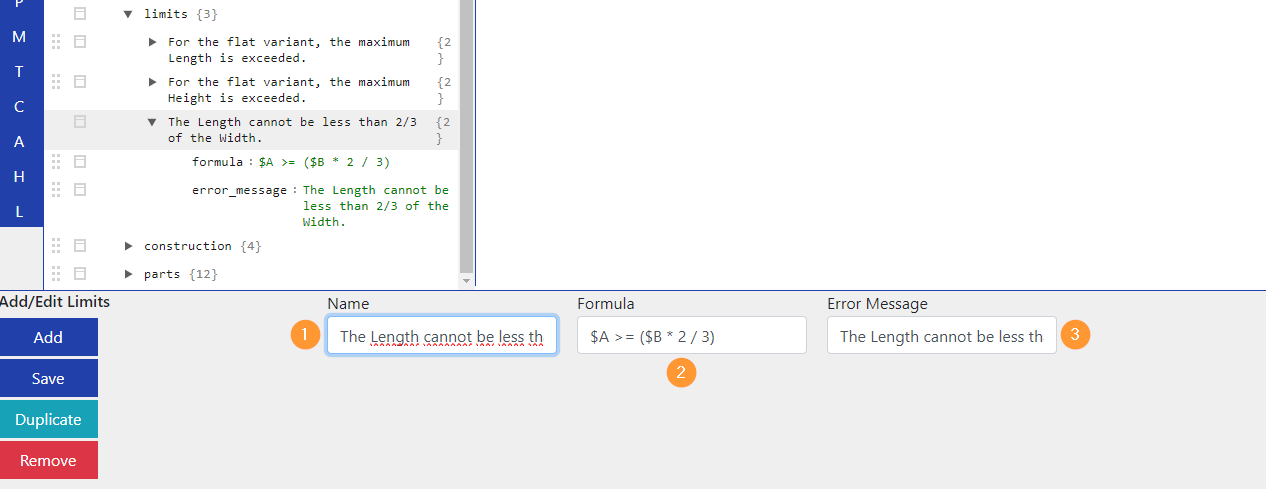
(1) You can enter a name for your limit here. In the example, the name corresponds to the text of the message, but can be any name as the customer does not see it. Example:
The Length cannot be less than 2/3 of the Width.(2) The formula is entered here. Example:
$A >= ($B * 2 / 3)→ Broken down, this means that variable A (length) must be greater than or equal to two thirds of variable B (width), otherwise the message will be triggered. As soon as the customer enters a number that makes A smaller than two thirds of B, the message appears.(3) shows the text of the message that the customer receives if the limit is exceeded or not reached. Example:
The Length cannot be less than 2/3 of the Width.
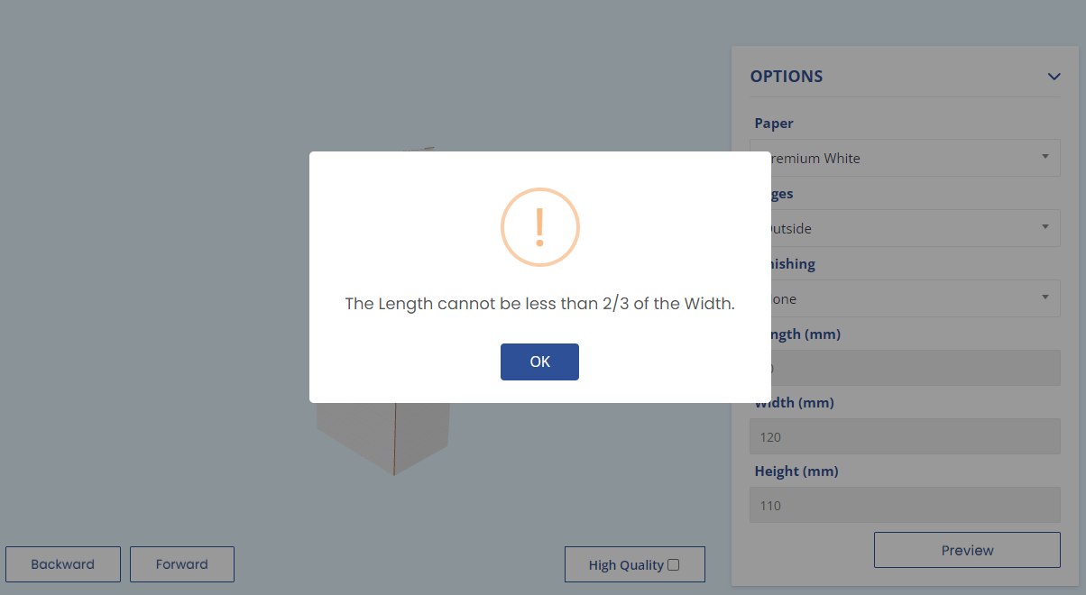
The frontend message then looks like this and can of course be freely translated again:
You can also enter concrete numbers in the limits (e.g. $B >= 100), just as minimum and maximum values can contain formulae. However, the latter always refer to the value of the variable in which they are entered, whereas limits offer greater leeway.
If the product part has been assigned a format in which one or more dimensions are outside the limits, minimum or maximum values from the start, one of the messages appears directly when the product page is loaded. In this case, either the format or one of the restrictions would have to be adjusted so that all dimensions of the format are within the permitted values.
Meshes and Animations
There are two separate documentations for meshes and animations.
How to fold the 3D model manually: How to fold packaging models
How to redefine meshes: How to reconfigure meshes for packaging models
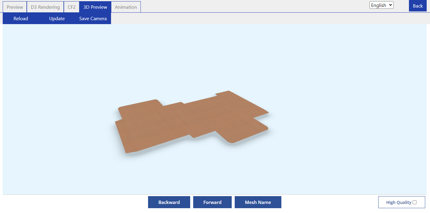
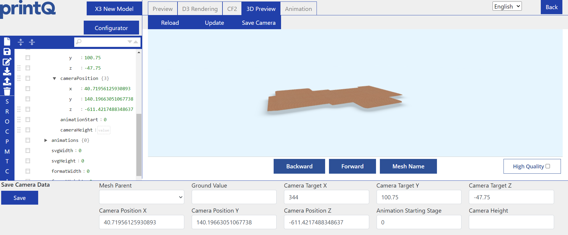
Camera
The camera comes into play with the 3D model.
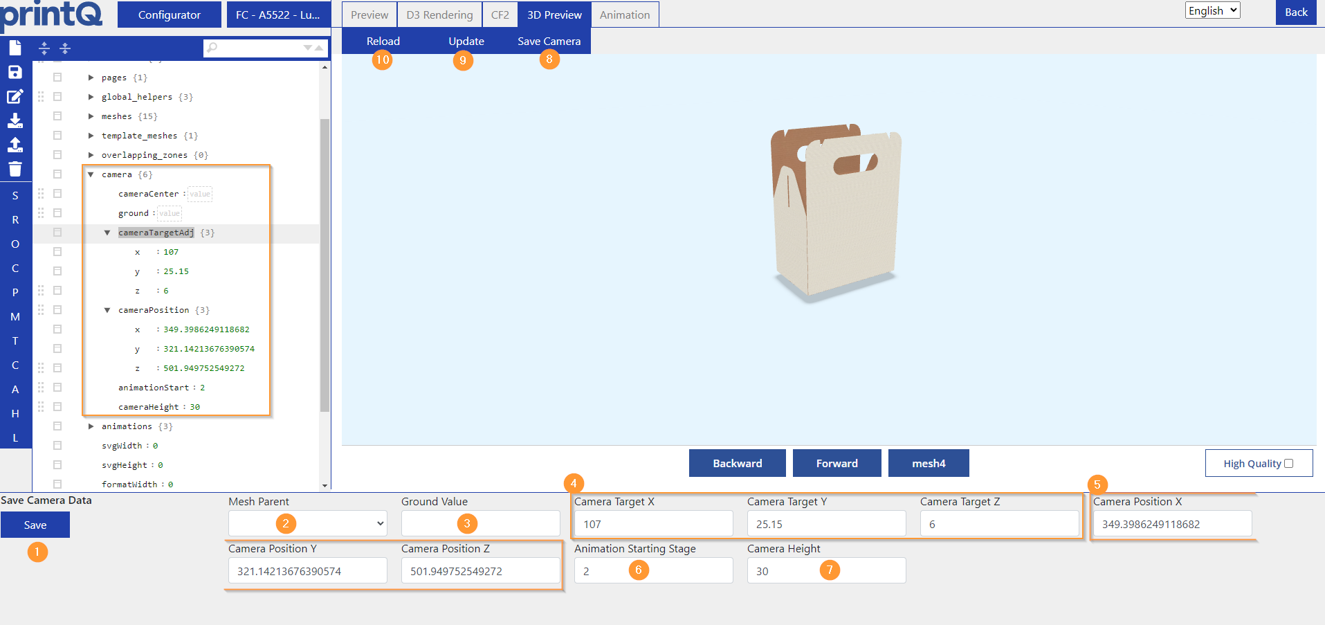
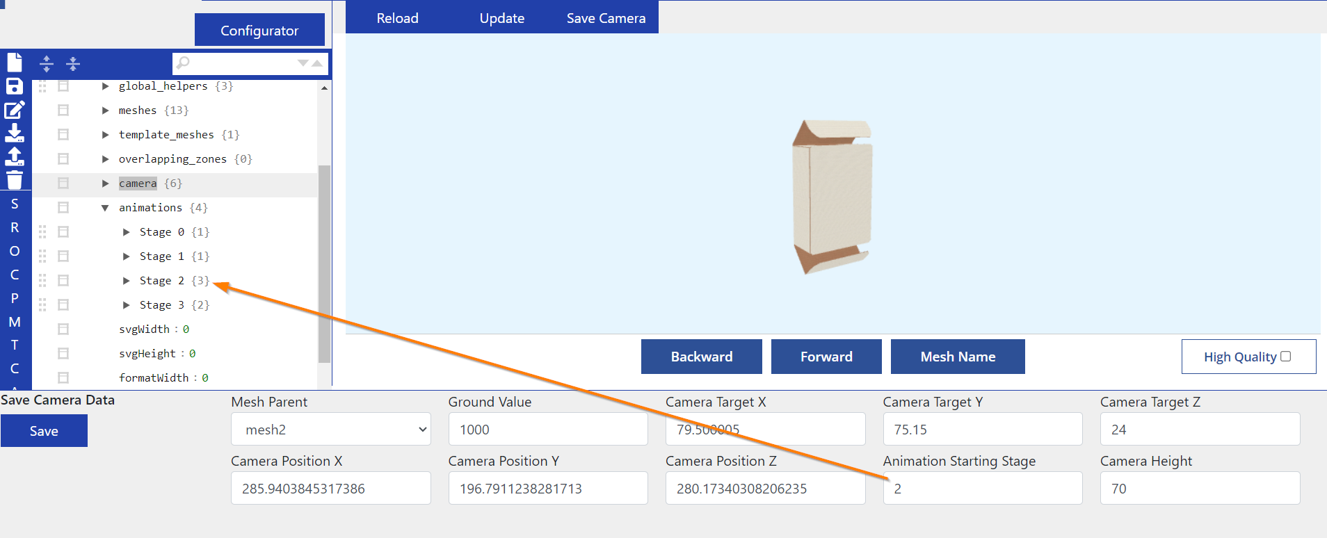
(1) saves the camera settings.
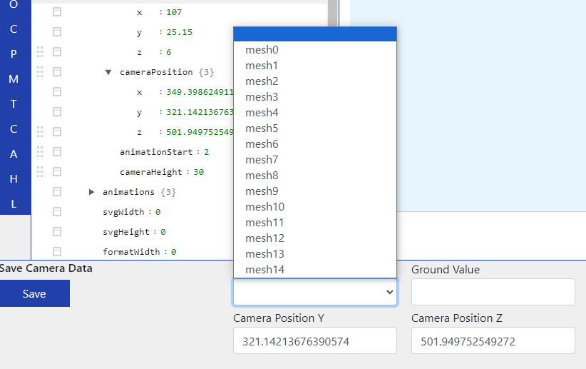
(2) shows all available meshes. Can be left blank to leave the camera focus on default. If you want to focus the camera on a specific mesh, select the mesh here. Depending on the model, the number of meshes varies and they must be entered under meshes in order to appear here, otherwise the dropdown will remain empty.
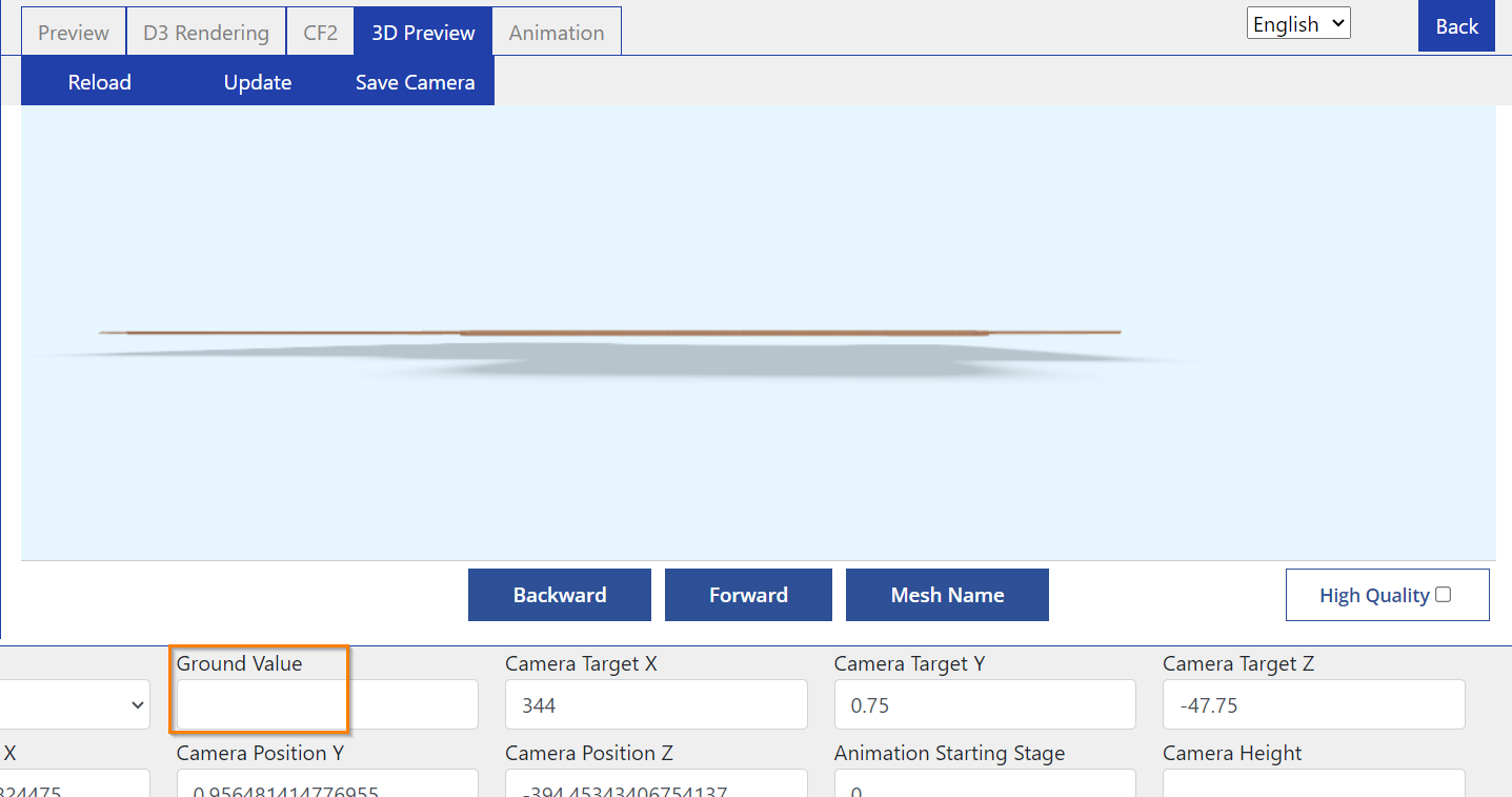
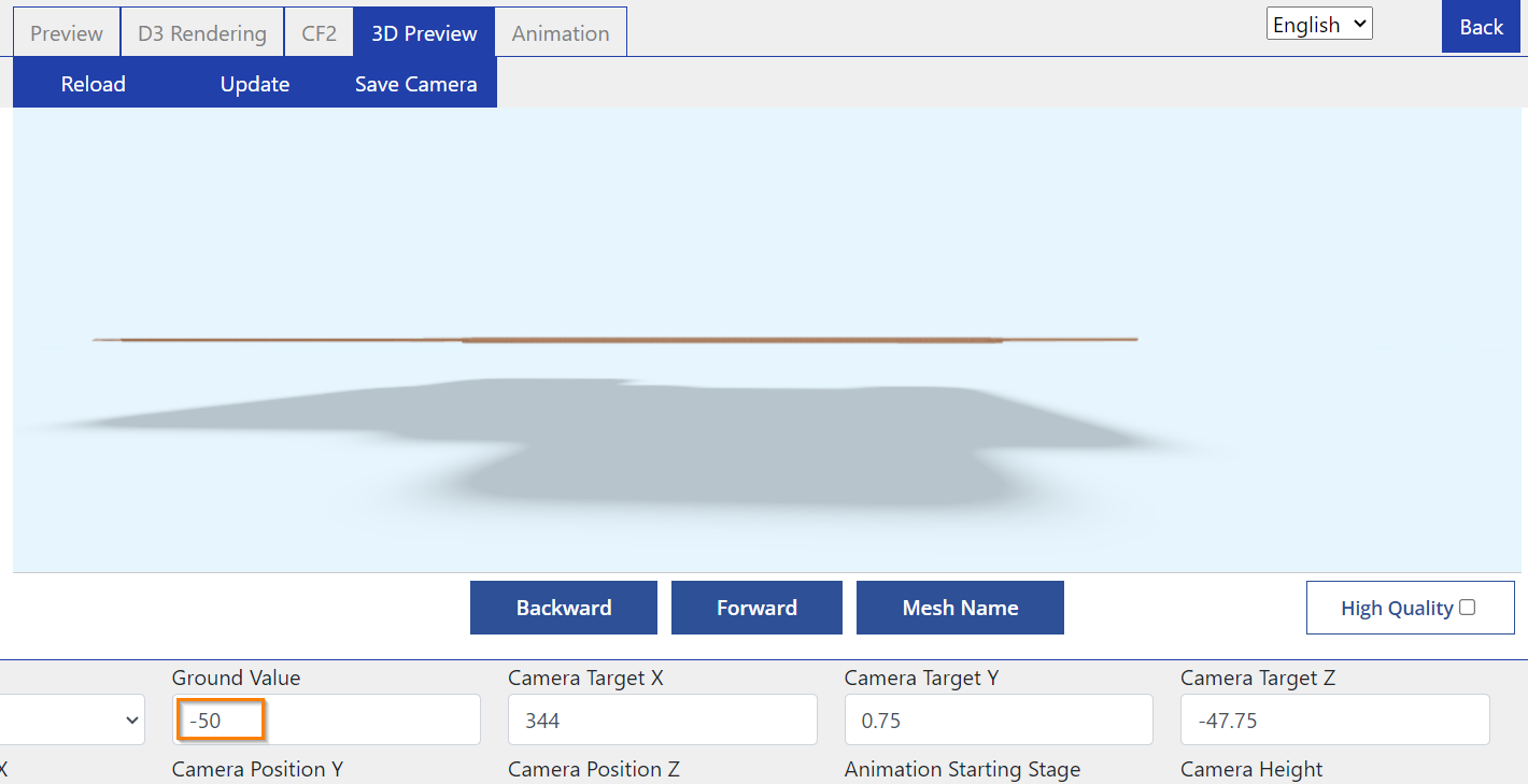
(3) specifies how far away the shadow is from the 3D model. As long as no value is entered, the shadow is very close to the 3D model by default. The higher the negative number entered, the further down the shadow moves. A positive number moves the shadow further upwards.
(4) These 3 values indicate the position of the object, i.e. the 3D model.
(5) These 3 values specify the position of the camera.
(6) specifies at which folding stage the model should be loaded. Only possible if you have entered the folding manually as the automation does not have any selectable stages.
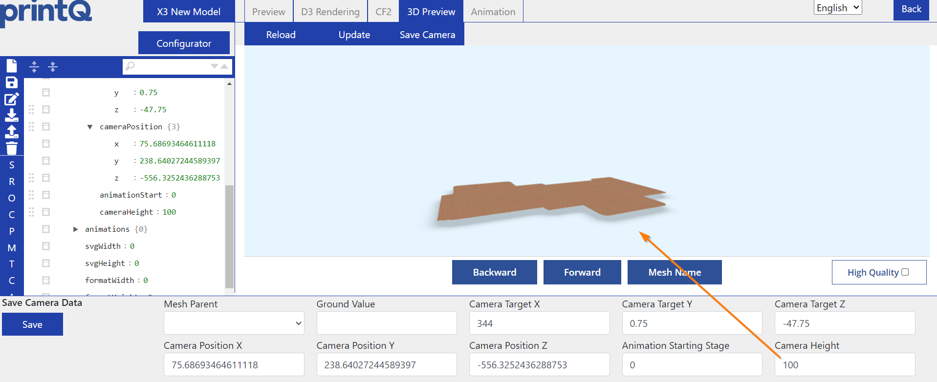
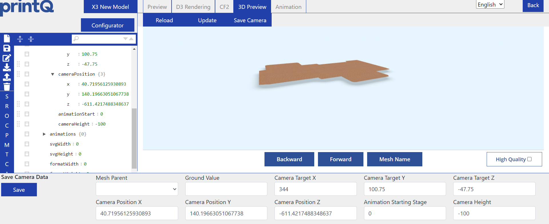
(7) specifies how far the 3D model should be shifted upwards (negative numbers) or downwards (positive numbers). No value is entered by default, but depending on the model, folding and positioning, it is possible that the upper or lower part of the 3D model is not fully in the frame when it gets unfolded. This setting allows you to move the 3D model up or down as required, just make sure that it does not disappear completely from the frame.
(8) As soon as you have positioned the box, you can save the camera with this button so that the 3D model is displayed exactly in this position and at this folding stage the next time it is loaded.
(9) If you have changed something in the camera settings, e.g. the ground value, you can update the view with this button. However, not all changes are updated, so we recommend using (10).
(10) reloads the whole 3D view and displays all changes saved via the discette, including updated steps for folding under animations in the table on the left.
Overlapping Zones
There is a separate documentation on this topic which you can find here: Overlapping Zones for Packaging
Template Meshes for Template Gallery
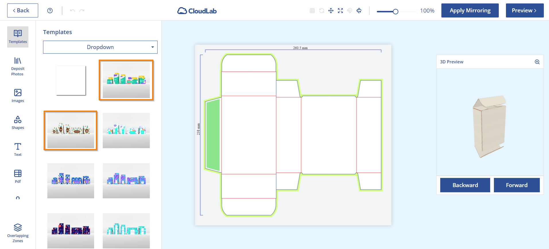
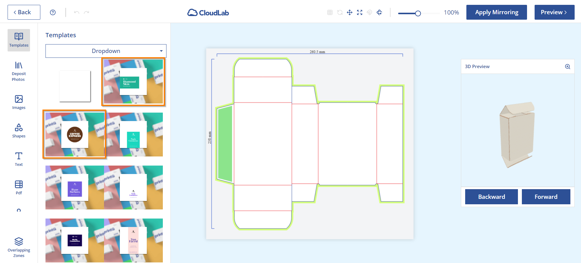
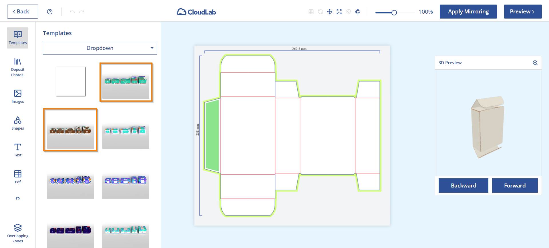
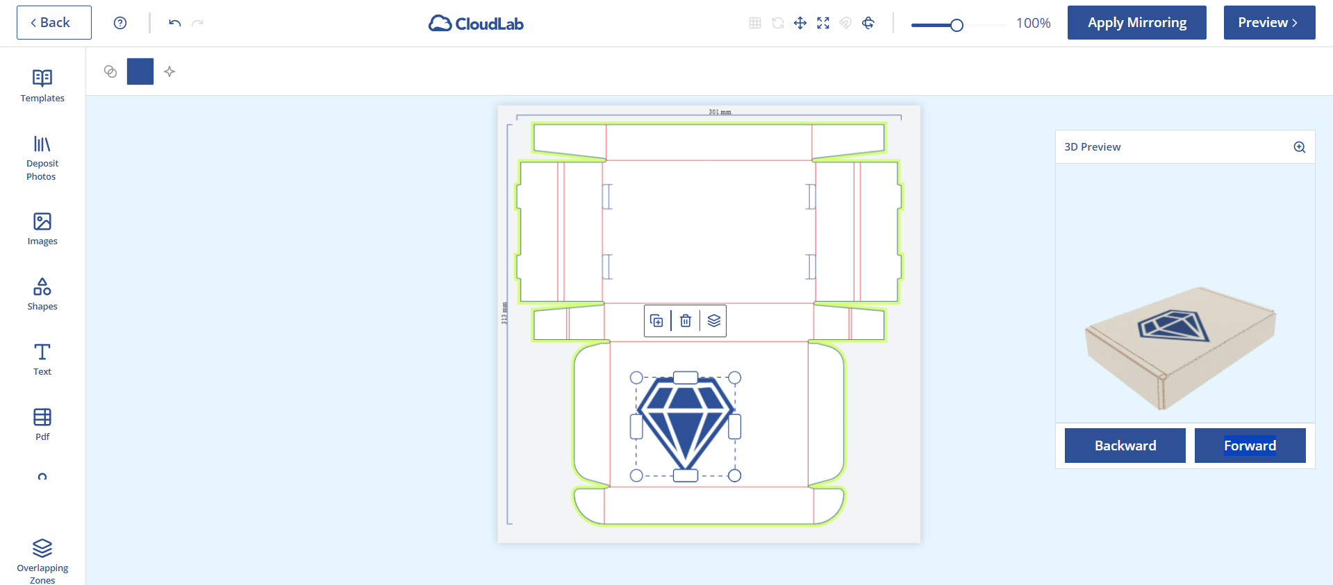
If you have created a new model and want to use it in the Template Gallery, it is necessary to map the template meshes so that the designs can be successfully applied to your model.
You can find a separate documentation on preparing the template meshes here: https://bridgeinteractive.atlassian.net/wiki/spaces/OP/pages/2968453121
Templates and page options
Special templates and settings are required for packaging products, which are already available on X3. We will take a look at the settings made here so that you can reproduce them if necessary.
First, let's go to the page option Pages.

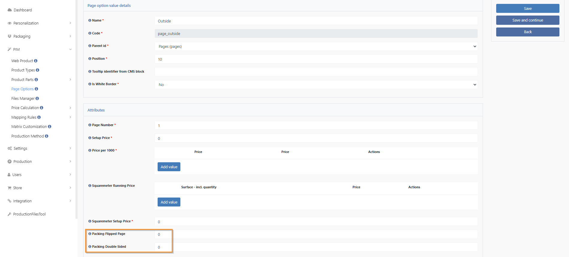
Here we enter two additional attributes (already available on X3).
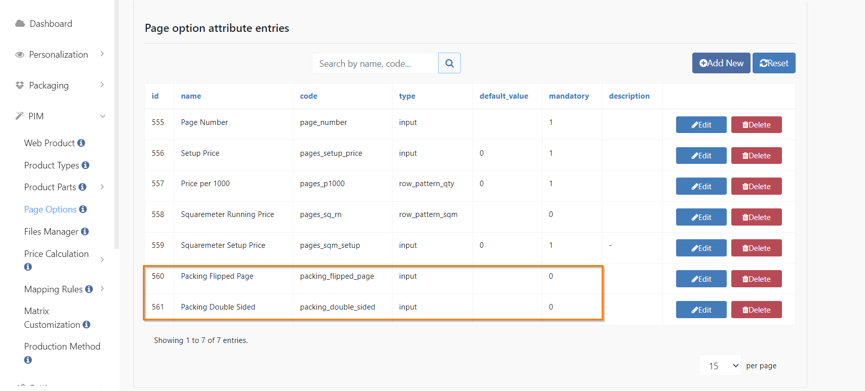
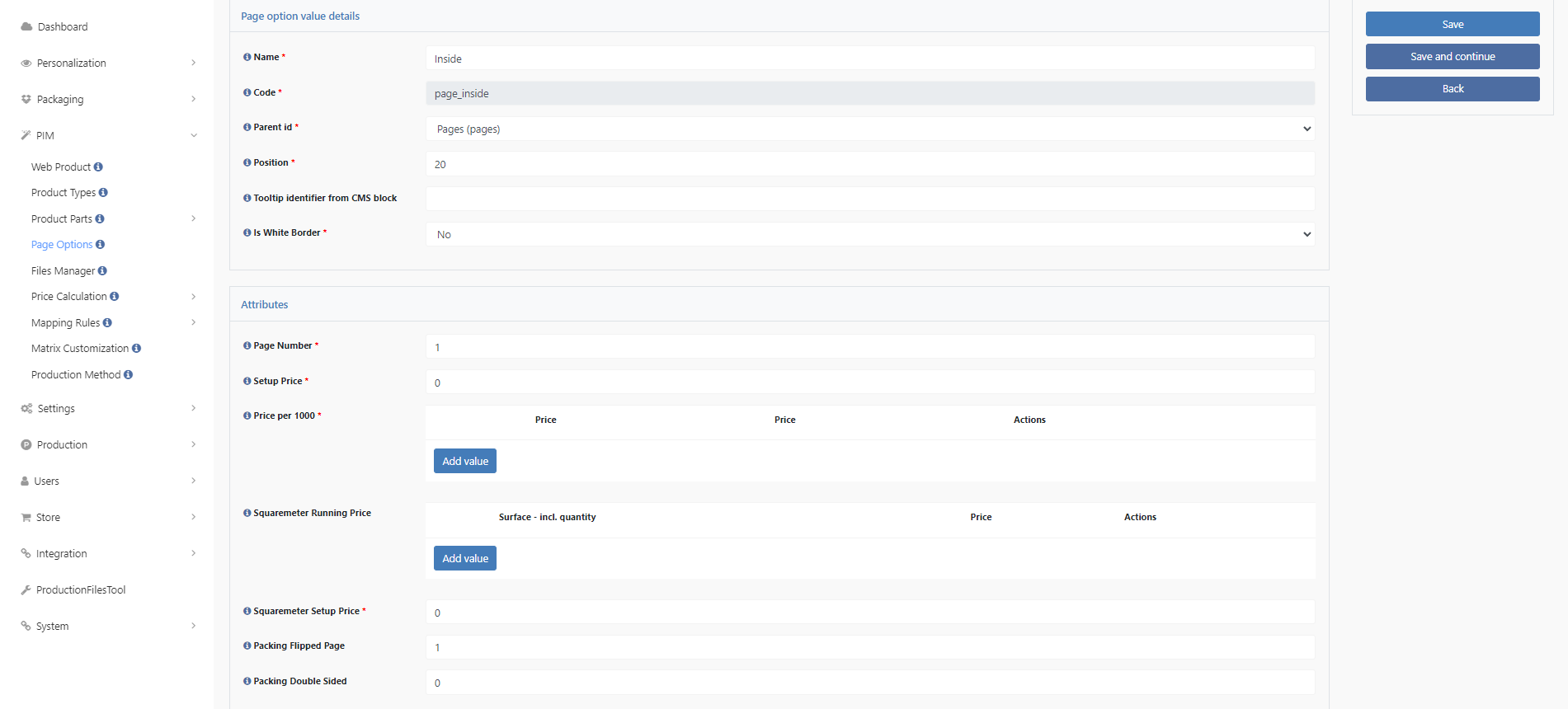
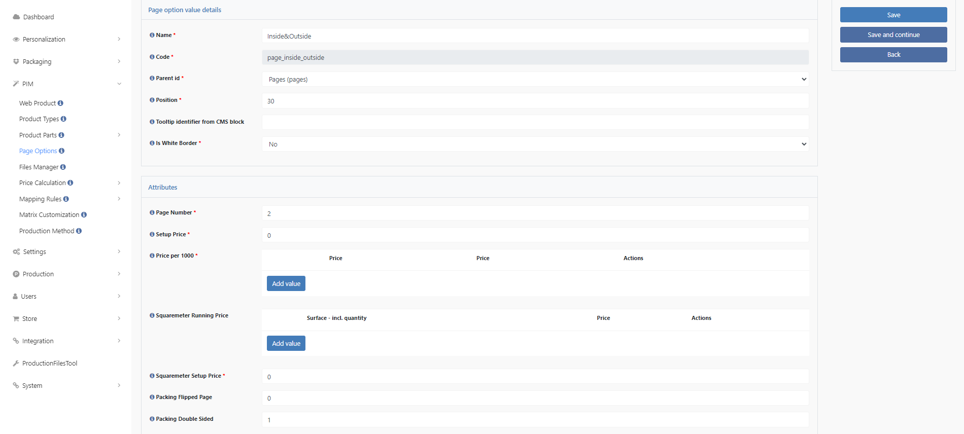
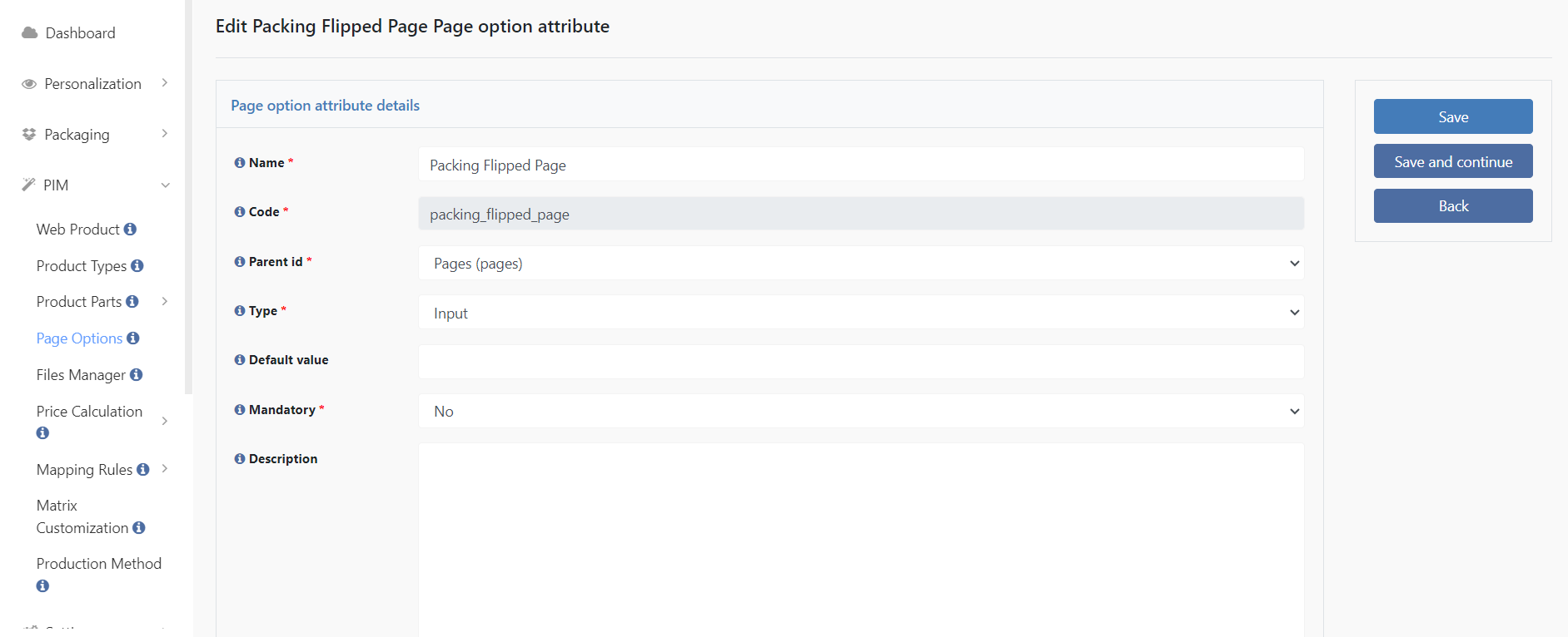
Packing Flipped Page is used to apply designs to the inside of a packaging in the frontend.
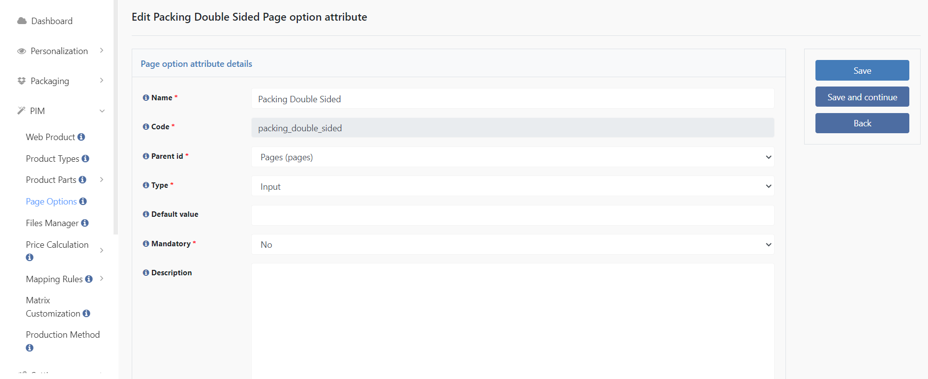
Packing Double Sided is used in the frontend to apply the designs to both the inside and outside.
Once these attributes have been added, we move on to the templates, where we create 2, 3 or 5 new templates (already available on X3).
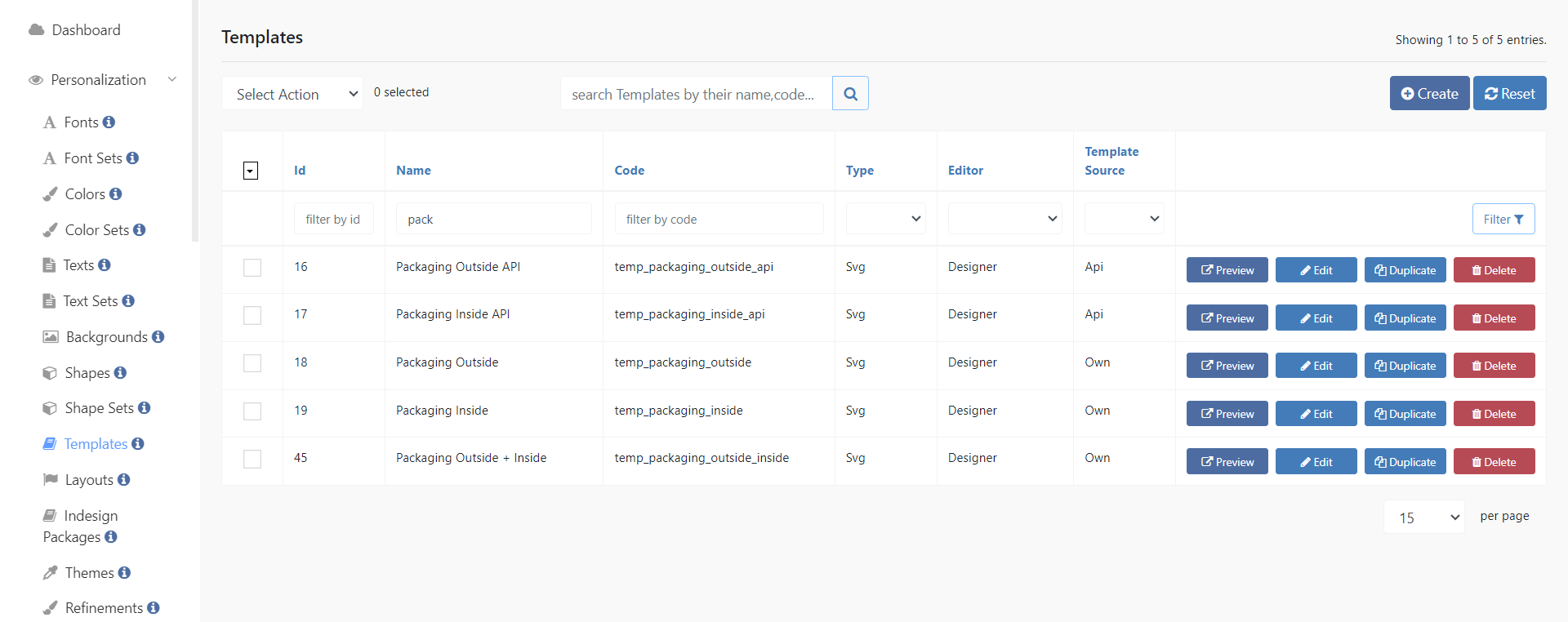
Two of these are used exclusively for the API and therefore for the Template Gallery. The remaining three are used without the Template Gallery, for example for overlapping zones.
Please note that the preview cannot be used with these templates because the product draws the 3D model from the Packaging Editor, not from the templates. The templates are important for the pages.
For API, there are templates for Outside and templates for Inside. Outside + Inside is only available for non-API products in the standard system, which is why three templates have been created for those.
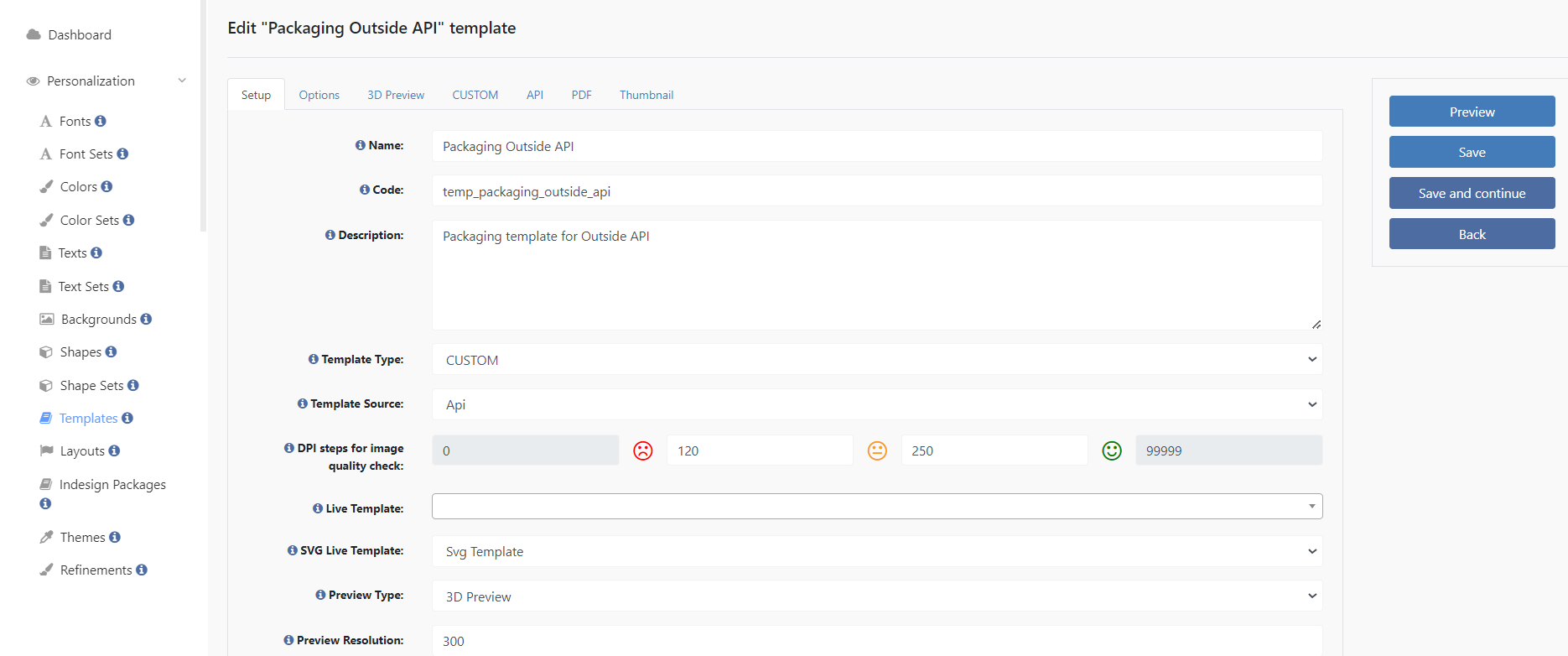
It is important to set the API templates in the Template Source to API and the Template Type to Custom, as was done in the example above.
Under 3D Preview, the 3D model is irrelevant because, as already mentioned, it is pulled from the Packaging Editor via the web product. However, the 3D data is of interest to us at this point.
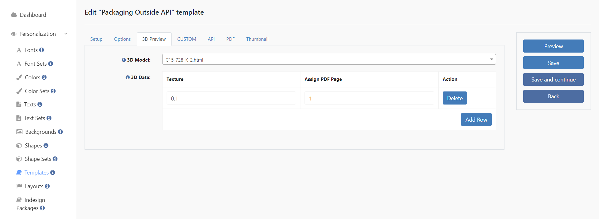
Here we enter that this template should map the designs to the outside of the 3D model by assigning the correct texture and page. For the outside, it is texture 0.1 and page 1.
For the inside, it is texture 0.0 and once again page 1.

For non-API templates, the template type is again Custom, but the template source is Own.
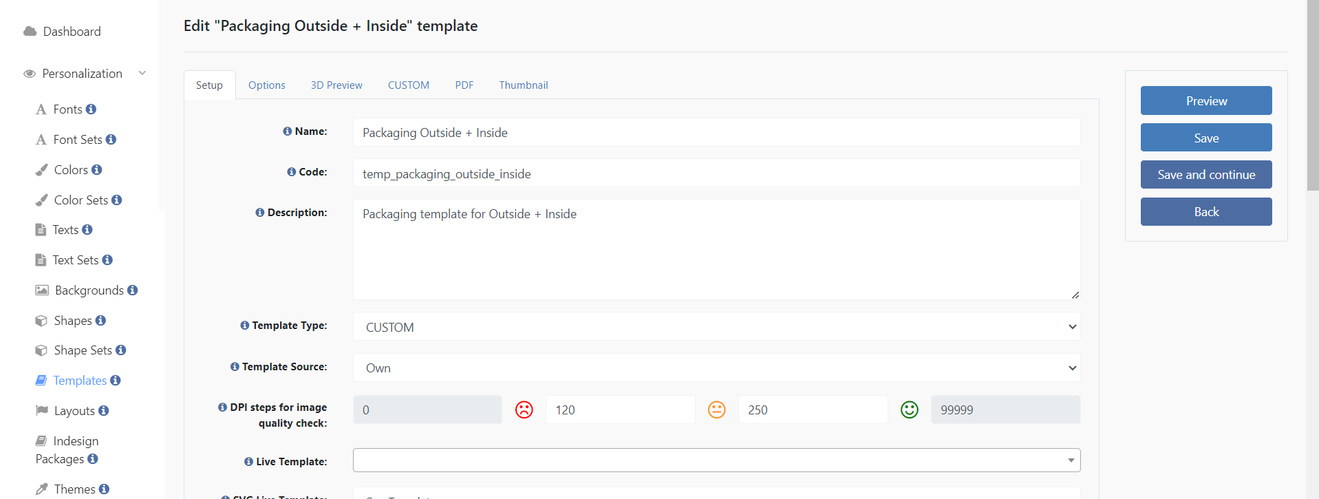
In the 3D preview you enter exactly the same as in the API templates, the only difference is in the template that combines Outside + Inside.

Two pages must be assigned here, one outside and one inside, which is why there are two lines. 0.1 is assigned to page 1 again, but 0.0 is assigned to page 2 this time.
Finally, only the template mapping needs to be done so that the system knows which template (outside, inside or outside + inside) it should open as soon as the customer selects the corresponding option in the frontend.
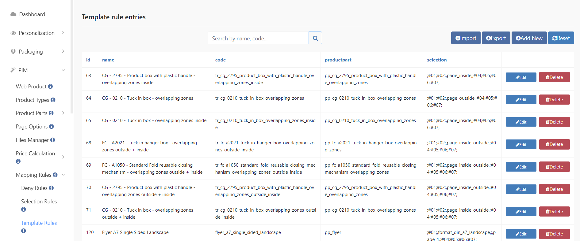
The result of the configuration of the templates you can see here on the upload (it works the same for persoanlization):
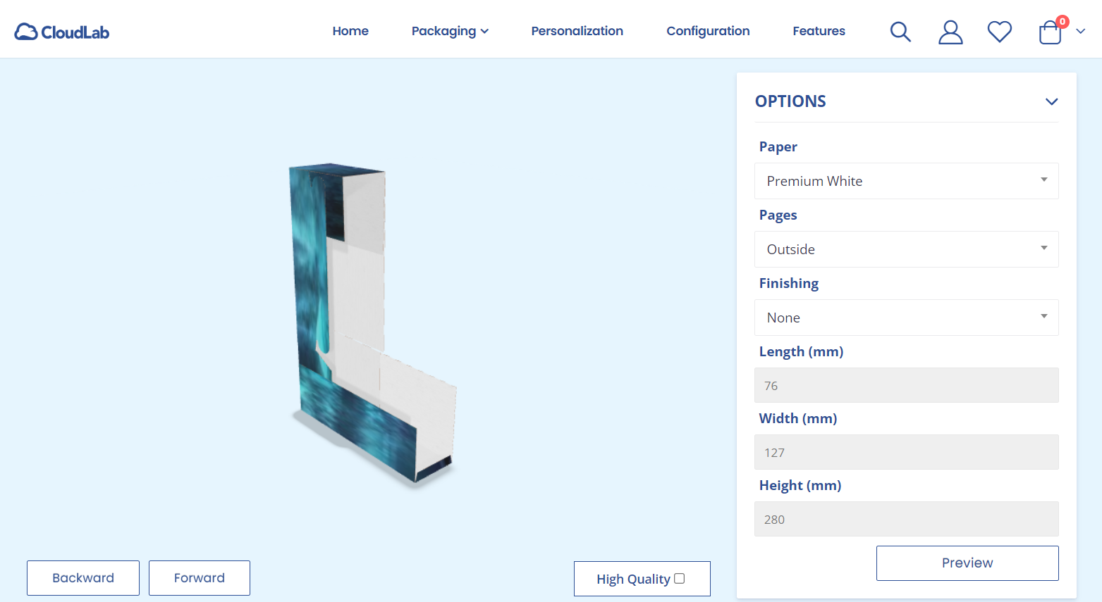
Outside
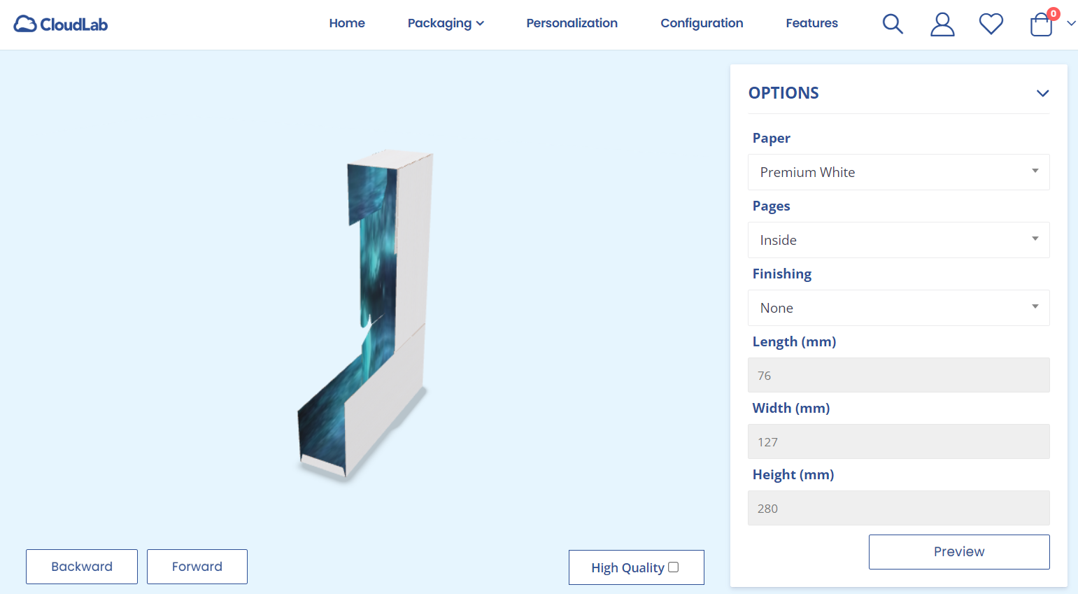
Inside
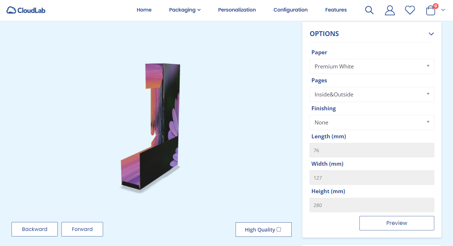
Outside + Inside
Please note that the upload for Outside + Inside expects a two-page PDF. If your PDF only has one page, it will only map the outside because there is no design for the inside.
Related topics:
How to reconfigure meshes for packaging models
https://bridgeinteractive.atlassian.net/wiki/spaces/OP/pages/2968453121
