Packaging - Example: 3D model with customizable window section
In addition to regular packaging, the editor also allows you to create packagings with cut-out windows. Using the above explained enabling of parameters for modification by the customer as well as associated rules, such a window can be freely positioned and customized in its size by the customer.
In the model files with windows these cutouts can be found under “Pages – Cuts” (selectable in the path structure on the left). After selecting, all existing cuts in the model rendering are highlighted on the right.
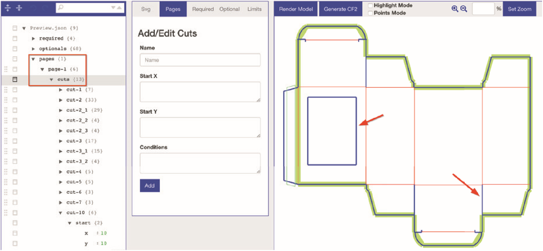
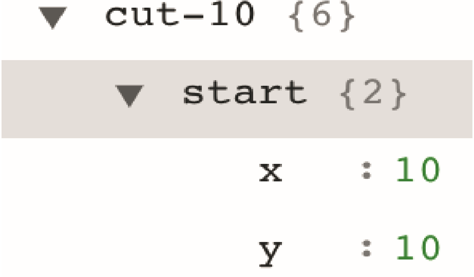
In the respective cuts, the values for the individual lateral lines (lines) can be set. In order to find the desired cut, we recommend you to activate the Highlight Mode mentioned before. In this case, cut-10 is the relevant cut for the window in the package.
The additionally specified start point for the calculation of the cut for the window is its upper left corner.
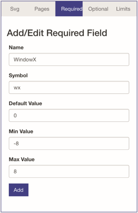
In order for customers to be able to move and freely position the window, variables must be created for the x and y axes. This is done as described above in the section „Required“.
The procedure for the x-axis is as follows here: Name and symbol can be chosen freely, e.g. WindowX and wx. The default value is specified as 0, so that the packaging has the original dimensions when called. Min Value and Max Value then determine how far the window can be moved horizontally. Once everything is set, the field is saved.
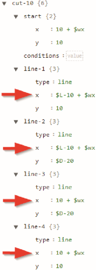
Now the variables must be assigned to the start point and the lines accordingly: For the start point, instead of a fixed value, the combination „[Value] + $[x-axis symbol]” must be entered in the path structure (with the above symbol here e.g. “10 + $wx”). Thus, the modification value entered by the customer is added to or subtracted from the current value.
This must then be done for all four line coordinates in order for the whole section to shift.
If you want for the window to also be movable vertically, you need to repeat the process analogously for the y-values.
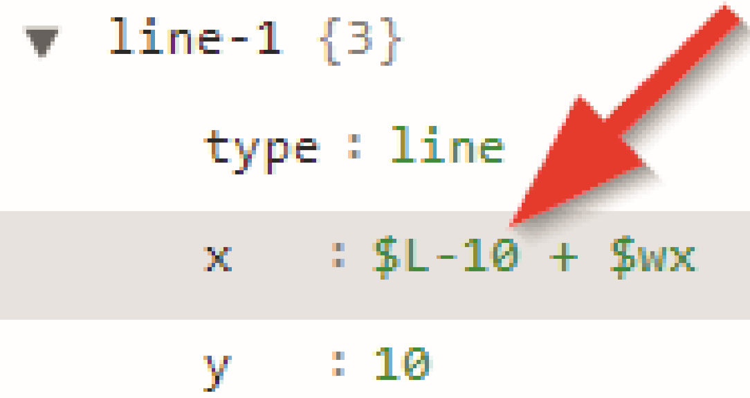
In order to enable the customer to make the window wider, narrower, higher or lower, you proceed in a similar way: Again, a new “Required” field is created, with a freely selectable name and symbol (such as WindowWidth and wb). The default value then corresponds to the default width of the window, which is already available and indicated in the x specification of the lines (here: 10).
Min/Max Value represent the maximum and minimum width of the window.
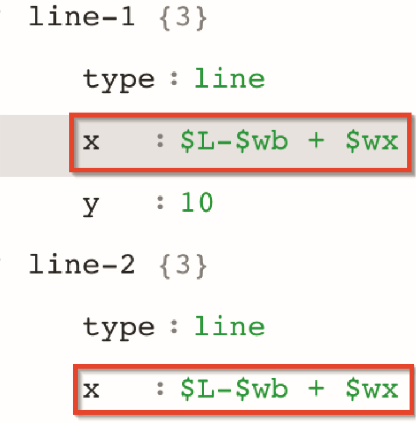
Then the parameters of the lines must be completed with the variables, taking both possible changes (positioning and size) into account in the calculation. Thus: “[Standard Width – Customer Width + xPosition]“ (with the above mentioned variables “$L - $wb + $wx”. This works the same way with the height of the window). Of course you can additionally set limits for all these parameters, as described above. This ensures that customers can only enter values which correspond to themeasurements and the quality of the packages.
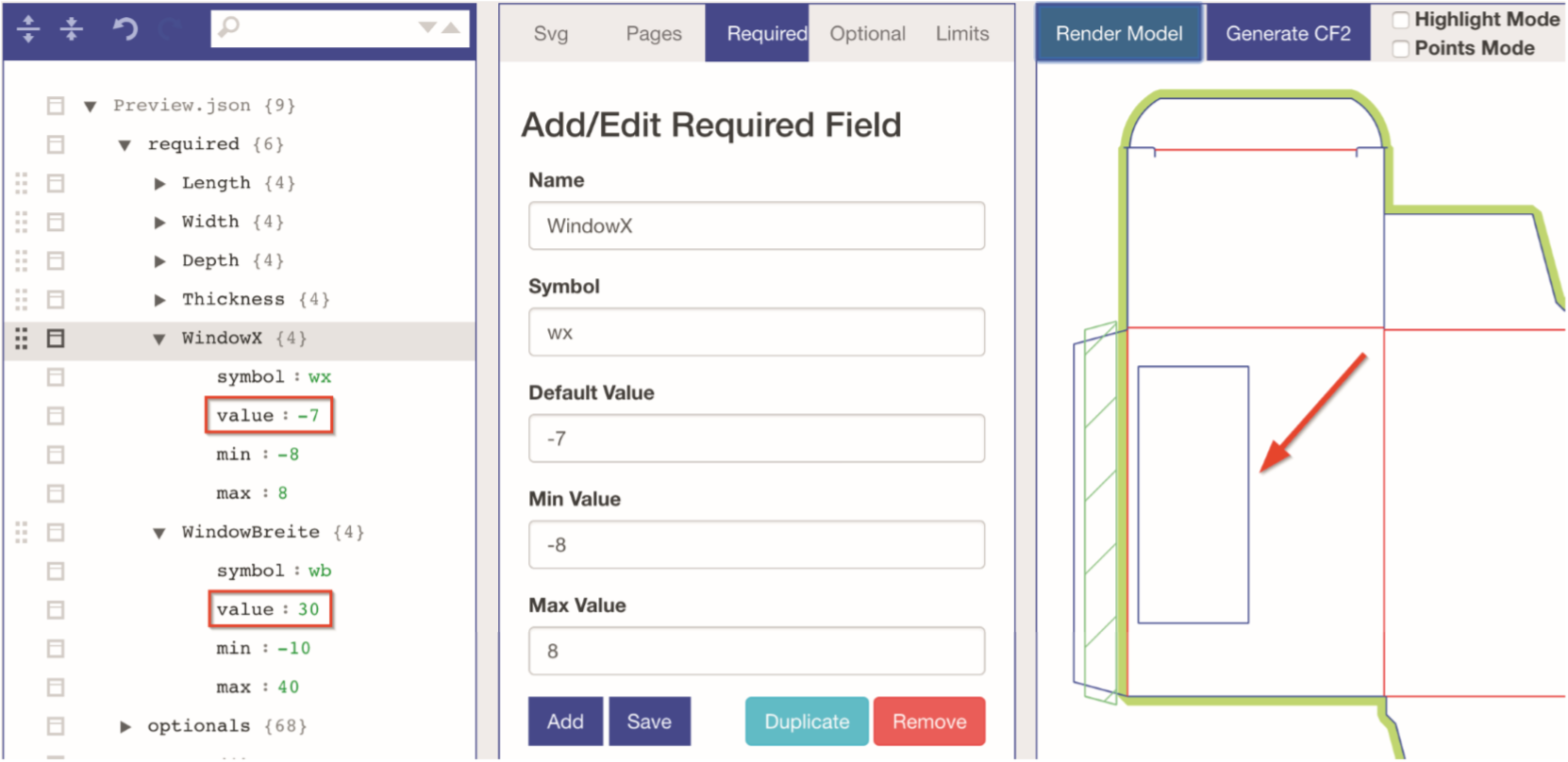
To check this, you can change the “Value” in the “Required Variable” and then click “Render Model”. The changes you made will then appear in the display window on the right. In this example the window was moved to the right and made smaller.
Save the model once you‘re done with the settings. We recommend to save the model under a new name, because otherwise you will overwrite the original model. Enter a new model name and save your new model by clicking “Save As”. If you wish to overwrite the current model, use the “Save” button.

